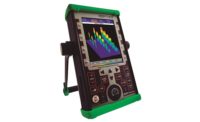
Now the field of ultrasonic nondestructive testing (NDT) is taking another step forward. Thanks to advances in digital signal processing software, new portable ultrasonic devices are emerging that can--for the first time--provide simultaneous thickness measurements of multiple material layers in a test piece. Additional advances enable precise gaging of extremely thin multilayers not previously measurable by ultrasonic instrumentation.
These capabilities are being developed to meet quality control needs for a growing range of manufactured products and components. As a result, ultrasonic thickness gaging is likely to find increasing application on the factory floor by industries that range from automotive and aerospace to appliances, packaging and pharmaceuticals.
Ultrasonics basics
Ultrasonic NDT takes its name from its use of sound frequencies that are higher than the 20 kilohertz (KHz) upper limit that is generally audible to humans. In ultrasonic thickness measurement, frequencies between 500 KHz and 20 megahertz (MHz) are traditionally employed, although higher frequencies up to 200 MHz may also be used for specialized applications.
Conventional ultrasonic thickness gaging works by measuring the round-trip transit time of a high-frequency sound pulse as it travels through a material. An ultrasonic transducer that generates bursts of sound energy is coupled to one side of the test piece. Sound waves traveling through the material reflect off the far side and return to the transducer. The gage precisely measures how long it takes for the echo to return, and then, using programmed information on the speed of sound in the test material, it calculates and displays the thickness of the part. Material thickness can often be measured to accuracies better than I0.001 inch (0.025 millimeter), with access to only one side of the material required.
This approach works well in the majority of gaging applications involving common engineering metals, plastics and ceramics, as well as in rubber, fiberglass, composites, and even liquids and biological materials. However, in a growing number of cases, manufacturing quality control requires measurement of very thin material layers that cannot be read by conventional ultrasonic gages. It is in these cases that newly developed approaches involving frequency-domain signal analysis or use of very high test frequencies may offer a convenient solution.
One common application involves thickness measurement of gas barrier layers in multilayer plastic products such as beverage bottle preforms, food and pharmaceutical containers, and automobile fuel tanks. The use of multilayer construction in such products has increased dramatically in recent years.
Produced by a process called coextrusion, these products will typically be made of two layers of a common and inexpensive plastic such as high density polyethylene (HDPE), polypropylene or polycarbonate, with one or more "barrier" layers in between. The barrier layer is typically made of ethylene vinyl alcohol (EVOH), polyvinylidene chloride, polyester, acrylic copolymer or proprietary materials. It is usually quite thin, often under 0.004 inch (0.1 millimeter). The usual purpose of the barrier layer is to prevent the slow migration of gasses through the container wall, or to prevent transmission of damaging ultraviolet light.
Physics barriers
While appropriately programmed conventional ultrasonic gages can readily measure the depth of the barrier layer, it is often not possible to measure its thickness with such instruments. There are two reasons for this, both related to the physics of sound waves.
First, as a test piece gets thinner, higher frequencies must be used to separate the backwall echo from the initial pulse, and typical conventional gages are not designed to work at the frequencies above 20 MHz that are required to resolve thin barrier layers.
For multilayer products such as preforms and gas tanks, however, a second, and more significant problem is that the plastic materials used are relatively poor transmitters of high-frequency sound waves. This means that it is often not possible to penetrate the surrounding structural plastic at a frequency high enough to resolve the barrier. At frequencies that do penetrate the material--which are typically below 20 MHz--the echoes from the front and back of the barrier layer overlap and cannot be distinguished by conventional methods.
Because of these realities, conventional ultrasonic instruments that rely on time-based measurement generally can't be used for barrier thickness gaging (see Figure 1). However, measurement of pulse transit time is not the only way to determine the thickness of a thin layer of material bounded on both sides by another material. It is also possible to use frequency domain signal analysis, a technique that is now being introduced to handheld, portable ultrasonic gages.
The frequency-based algorithm works by observing the interference between the signals being reflected from the front and back interfaces of the barrier layer. These two signals run into each other, and destructive wave interference occurs when the thickness of the layer is an integer multiple of half-wavelengths of sound. The gage uses a broadband transducer to generate a sound pulse that is coupled into the test piece, and it digitally stores and then analyzes the echo received from the barrier layer.
By comparing a fast-Fourier transform (FFT) of the frequency spectrum reflected from the barrier layer against the FFT of the frequency spectrum initially generated by the transducer, the instrument detects spectral null points. Because the speed of sound in the test material is known, and because wavelength is derived from velocity divided by frequency, the gage can then calculate from the frequency of the null points the thickness of the layer that generates them.
All in one
As an added convenience, a modern digital gage can operate in both time and frequency domain modes to permit simultaneous measurement of all three layers in a typical coextrusion, even when sound velocity in the layers is different. The gage can be programmed to simultaneously display the thickness of each individual layer and the total thickness of the part. This is especially useful in situations in which the thickness of the barrier layer, the depth of the barrier layer and the total thickness of the part must all be monitored and controlled. A sketch of a three-layered plastic part being measured with a typical instrument display is shown in Figure 2.
The time interval between the first and second echo is used to measure the thickness of the first layer, 0.1237 inch in the figure. The second echo represents the overlap of two signals, and thus is used to measure the thickness of the barrier using the frequency-based algorithm. In this example, the barrier thickness is 0.0089 inch. The thickness of the third layer is also measured using the time-based technique and displayed as 0.1207 inch. Finally, the gage calculates and displays the total thickness of the part, 0.2533 inch.
The accuracy of the frequency-based measurement was determined using control samples, manufactured with a thin-barrier layer and sandwiched between two thicker layers. The inner barrier layer was measured directly, using high-frequency ultrasound, and those readings were compared with measurements obtained using the FFT algorithm. The standard deviation of the measurements was about 3%, which is the current resolution limit of the measurement.
A commercial multilayer gage was tested with automotive tank samples with varying barrier-layer thickness. The test was performed on more than 60 samples with thickness ranging from 0.0044 inch (0.11 millimeter) to 0.0154 inch (0.61 millimeter). The overall standard deviation between the quality control numbers and the ultrasonic measurements is now a function of multiple parameters: ultrasonic measurement accuracy, quality control accuracy and variations in ultrasonic velocity resulting from temperature and barrier chemical composition variability. The overall standard deviation was within 10%.
Fast and accurate multilayer measurement is not limited to applications involving thin barrier layers. For example, aircraft windshields are typically made up of two relatively thick layers of acrylic or similar hard plastic sandwiched around a thinner layer of a soft material such as polyvinyl butyral (PVB) that relieves thermal stresses. The hard plastic layers are typically about 1/2-inch thick, while the PVB layers often measure about 0.05 inch. Laminated safety glass for automobile windshields likewise consists of two layers of glass surrounding a soft polymer layer such as PVB that prevents shattering if the glass is broken.
In both cases, the sound velocity of the material in the middle is significantly slower than that of the inner and outer layers. Because the polycarbonate materials used for the outer layers are relatively transmissive, a 5 to 10 MHz transducer can be used to penetrate the material, and can also resolve the less transmissive but still relatively thick inner layer. This means that FFT-based analysis is not required; traditional time-based ultrasonic measurement can be used to gage both the inner and outer layers.
Quick reads
In the past, however, the velocity differential among the layers prevented accurate one-step measurement; conventional ultrasonic gages require different setups to measure each of the three layers individually. But the latest ultrasonic gages rely on software methods to alleviate that burden. Thanks to the flexibility offered by digital processing, this new generation of multilayer gages can read each layer, as well as total thickness, in one quick measurement.
Another common multilayer measurement application involves gaging individual layers and total thickness in coextruded engineering thermoplastics such as acrylonitrile butadiene styrene (ABS) and acrylic, where a combination of materials is used to optimize physical properties and appearance. Examples include plastic window frames, refrigerator shelves and other components in which base materials are coated with a thin outer layer for aesthetic or cosmetic purposes. Cap layers as thin as 0.008 inch (0.2 millimeter) as well as thick substrate layers can usually be measured simultaneously using ultrasonic methods. The one area where this technique is limited is in coextrusions involving foam layers. Because foams will not support high frequency sound waves, generally only the cap layer can be measured.
Advances in digital software development are also making ultrasonic gages more user friendly for thickness gaging tasks involving very thin coatings. Multilayer automotive paint systems--which typically employ a primer coat, a color coat and a clear coat, each less than 0.002 inch (0.05 millimeter) thick--are one potential application.
Traditionally, low-cost gages using electromagnetic techniques have been used for measuring total paint thickness on steel. But electromagnetic gaging methods are less well-suited to nondestructive measurement of individual layers.
For these kinds of applications, sound attenuation is not a problem for ultrasonic gages, and a direct pulse and echo technique can be used. The limitation of conventional ultrasonic gages in these cases is frequency. Resolving front and back echoes from coatings or other materials only 0.001 to 0.002 inch (25 to 50 microns) thick typically requires test frequencies of 100 MHz or greater, while common gages are typically limited to bandwidths no higher than 25 MHz.
Commercial instruments and transducers are now available that use ultrasonic frequencies greater than 200 MHz, permitting measurement of polymer layers as thin as 0.0005 inch (0.012 millimeter). And ultrasonic benchtop systems are now available that use these high-frequency components, along with sophisticated software to measure thin multilayers such as automobile paint. For each measurement, these systems store a digitized wave train that contains a series of echoes representing the reflections from each material boundary within the test piece. Operators use a series of software gates to identify echoes of interest, and also enter sound velocity values for each material. The software then precisely measures the peak-to-peak time intervals, and calculates and displays thicknesses.
The resolution and accuracy of the time measurement in these systems is significantly greater than that found in handheld gages. Transit time measurement accuracies that are better than I1 nanosecond and thickness measurements to a calibrated accuracy of I0.0001 inch (0.0025 millimeter) or better are possible. These systems can also be employed in material analysis applications to quantify small changes in density or hardness by recording small changes in sound velocity. Software typically accommodates a variety of statistical processing techniques as well, which can be applied to raw data for further analysis.
As with every other area of instrumentation technology, the development of signal processing and signal analysis software by manufacturers of equipment for ultrasonic NDT is an ongoing process. Undoubtedly this will lead to even further expanded capabilities in the future.
TECH TIPS
- Traditional ultrasonic thickness gaging works by measuring the round-trip transit time of a high-frequency sound pulse as it travels through a material.
- New, frequency-based software techniques are being added, allowing more capabilities, including the ability to simultaneously measure the thickness of multiple material layers in a test piece.
- Other software advances used with higher frequency transducers are allowing precise gaging of extremely thin multilayers not previously measurable by ultrasonic instrumentation.


