Important Considerations in Error Compensation

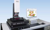
Abbé Principle: When measuring the displacement of a specified point, it is not sufficient to have the axis of the probe parallel to the direction of motion, the axis should also be aligned with (pass through) the point. Source: Mahr Federal Inc.
Recently, I was approached by a company interested in buying a sophisticated metrology system. They were comparing several different brands, and to be as thorough as possible, had set up a criteria matrix in which one of the questions was, “Is your machine error compensated, yes or no?”
“Well,” I said, “yes, it is” and promptly started to explain the error compensation strategy. That garnered a blank look. “But don’t you want to know what and how?” I asked. “No, thank you,” was the answer.
In fact, error compensation is an important consideration. No matter whether you are interested in a machine tool, a metrology system or another precision device that relies on mechanical motion, what errors of mechanical motion are compensated for and how they are compensated directly impacts that system’s ability to operate at the highest level of capability. It is really not a “yes” or “no” question.

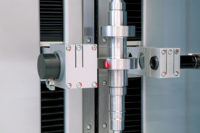
Abbé’s Offset is defined as the distance between the point of contact of a probe on the piece being measured and the axis of the position measuring system. Source: Mahr Federal Inc.
Sources of Mechanical Error
In the world of metrology systems, error compensation is generally considered to be the capability to apply corrections for undesirable or unplanned errors in positioning or motion. Typically, it is used for two reasons: 1) to increase the capability of the machine; or 2) to decrease the cost of manufacture for a given system.As metrologists we all want to build better machines, but the business side of us tells us that if a system can be built less expensively and yet reach the same level of capability through error compensation, it may be more competitive or more interesting for additional applications where previously the cost was prohibitive.
Excluding temperature, which requires separate compensation techniques, there are five different types of mechanical error.

Source: Mahr Federal Inc.
Abbé’s Offset is defined as the distance between the point of contact of a probe on the piece being measured and the axis of the position measuring system. In terms of simple measuring instruments, a micrometer is an Abbé-compliant device because the measuring system is perfectly in line with the probe, whereas a caliper, with its measuring point offset from the scale, is not.

Source: Mahr Federal Inc.
Development of Error Compensation
Errors of mechanical motion are nothing new, of course, and efforts to compensate for them have been around for many years as well. Early clockmakers had mechanisms to make their clocks more accurate, and “corrector bars” or “corrector systems” for both metrology systems and machine tools have been documented as early as 1760.But it is only in the past 30 years or so, with the advent of readily available and affordable computing technology, that error compensation has come into common practice. The methods available can be classified into three general categories-simple static, static plus dynamic and real time.
The same simple static approach can be used to compensate for errors of position and errors of angularity.
This brings us back to the customer who wanted to know if our machines were error compensated, yes or no? Which errors? Not all machine manufacturers compensate for all types of static error, and knowing which can be a very important consideration.
Even more important is how these errors are compensated. Looking again at the example of straightness, are the guideways measured using a laser interferometer or an optical flat? There are differences. These independent systems and artifacts are very good-most probably better than the machine-but even they are not perfect. However, there are techniques that can be used to improve compensation data accuracy. For example, make multiple measurements and use the redundancy in the measurements to separate the error from the machine and the error from the artifact, and find the errors of both.
With angularity errors, you have to measure the same kinds of things you do for straightness, but you also have to know about the geometry of your machine, how it is built, and what the distance is between the scale system and the probe tip. You need to know how accurate the scale system is, and whether the manufacturer mounted the checking system by the scale or the probe itself in developing the error compensation data file. If it was mounted on the scale, you may need to additionally correct for the probe geometry. Again, understanding what is being corrected and how it is being corrected has a major impact on the quality of the error compensation system, and ultimately on the accuracy of the machine.

Truly practical real-time error compensation requires enough computer power to process large amounts of data very quickly. Each axis or guideway of this system has a corresponding reference bar and each reference bar has a set of capacitor sensors that can measure all six degrees of freedom for that axis. Thus, if there is any pitch and yaw during movement down one guideway, the system can compensate for it immediately. Source: Mahr Federal Inc.
Next, rotate the cylinder so the traced side is opposite the column. Then mount a different probe and reach around the cylinder and trace the same path again. This profile, P2, also contains errors from the machine and the artifact, but those of the artifact are now reversed by 180 degrees. Add the two profiles together and divide the result by 2 to get the machine error without the effect of any errors in the cylinder.
However, as interesting as this theoretical possibility is, it has not yet been proven practical. Machine geometry is of such complexity, and the possible variations of part weight and motion are so numerous that machines that use such a system are not in commercial use. A number of universities have theorized about it, and tried to develop models to do it, but when they attempted to apply those models to machines, the results have always been: “it doesn’t work very well.”
If that sounds simple, it is not. For every axis in the machine that measures a part, there has to be some parallel type of system that measures what is happening to that axis as it is measuring the part. That is difficult to build without all these axes getting in each other’s way. But it can be done, and when the concept was first really put forth, it was referred to as having “a machine within a machine” or “a machine frame and a metrology frame.”

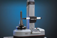
Using real-time error compensation, this system is designed to take reference quality 3-D and form measurements onto the shop floor. In addition to traditional form and position measurements such as cylindricity, concentricity and parallelism, the system also accurately measures diameter and angle on parts such as sealing cones, and a wide range of other features. Source: Mahr Federal Inc.
For modern machine tools and scanning metrology machines only a few examples of this exist in regular use. Most examples are in national laboratories and academic institutions. One of the earliest documented examples in the modern era is the large optics diamond turning machine (LODTM) at the Lawrence Livermore National Laboratory. This machine was developed in the days of the Strategic Defense Initiative-euphemistically known as Star Wars-when they needed to make very large, very high precision optics that could focus on targets and direct missiles, and where even very tiny angular errors had to be eliminated. The LODTM is a machine tool that uses a single-point diamond as the tool to remove tiny precise amounts of material from whatever it is that it is machining.
Lawrence Livermore reported in 1983 that they had a separate metrology frame around this machine that used laser interferometers to measure the positioning of the diamond turning system and was able to take into account things such as the cutting force of the diamond and the corresponding machine distortion. These LODTMs are considered by many to be the highest precision machining devices built to date.
Other examples from national laboratories and research institutes can be found throughout the world. These include a machine built by the National Standards Lab in Switzerland which used a machine frame and a metrology frame to provide super-high precision measurement within a very small volume-80 by 80 by 38 millimeters-for high-precision Swiss watch components. While interesting technology, machines such as this are of limited interest due to their lack of availability to industry at large.
With today’s computing power, a number of metrology systems for the measurement of form errors and gear tooth profiles are available which use real-time metrology frame-based error compensation, and they will become much more prevalent now that the computing technology is available to do it at a reasonable price and a reasonable speed. These machines offer the highest level of capability possible and render the simple questions such as what errors are present in the straightness of a machine guideway obsolete. By using these types of systems, the user is able to achieve real-world results at previously unattainable levels of capability.
If in the market for a metrology system, understand that error compensation is a good feature, but it is not a simple yes or no question. First, there are five sources of error and you need to worry about them all.
Second you need to know how the error compensation is being done, and even if it is just simple static, what techniques are being used and to what extent needs to be known.
Finally, if part weight or machine motion are factors in the measurement process, consider systems that employ real-time, metrology frame error compensation.
In short, instead of a “yes” or “no” check box on your criteria matrix, you should probably think about a matrix just for error compensation. Q
Tech Tips
Quality Online
For more information on error compensation, visit www.qualitymag.com to read the following articles:Looking for a reprint of this article?
From high-res PDFs to custom plaques, order your copy today!


