NDT Applications: Laser Adjusts Motion System of Ultrasonic Scanner

The Joint Strike Fighter (JSF), now under construction at Lockheed Martin, is being made in an assembly process like a car, drawing parts from many suppliers to feed a mile-long assembly line. The JSF is designed with complex 3-D surfaces produced from composites that do not reflect radar. Because of the complexity of these parts, they are manufactured via fiber-placement technology to near net shapes. Component manufacturers inspect parts with nondestructive test (NDT) systems to ensure that they do not hide flaws that can become stress risers during supersonic flight or high g-force turns.
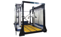
Matec Instruments (Northborough, MA) builds ultrasonic inspection robots that look through these parts to locate voids or delaminations. The instrument is based on two identical gantries that resemble the towers on a suspension bridge, each supporting a horizontal beam (a manipulator) that moves in X-Y directions. On the end of one manipulator, the machine carries an ultrasound transducer; on the end of the other is a receiver. Together, they work in a master/slave configuration. With a travel of 40 feet in the X-axis and 18 feet in the Y-axis, the system is an NDT scanner with a large inspection envelope.
The data quality produced by the scanner depends on careful positioning of the ultrasound heads during scanning. Because of their size and machining limitations, the manipulator drives cannot position the ultrasound transducers with the necessary accuracy. The ultrasonic image quality depends on the testing machine's ability to follow itself and the complex contoured geometry it is inspecting. When the system is performing a through-transmission test, each independent five-axis gantry must track the other while sending ultrasound from one side of the component through the thickness to the other side.
To do this, Matec chose the Faro Laser Tracker, a laser-measuring device from Faro Technologies (Lake Mary, FL) that measures large objects within a 230-foot range with a point accuracy of 0.001-inch. To make measurements, an operator secures the device to a tripod and beams the laser toward the target object. A handheld reflector is guided along the surface to be measured, and the beam is bounced back to the base unit. Using the pointing angle of the laser beam and the distance to the target, the unit's software calculates the position of each point. Measurements can be taken at a rate of hundreds of points per second. If the beam is interrupted, the software recaptures the beam without requiring the operator to start over.
The system provides a compensation table or map for each machine. Mapping takes place during machine setup and throughout the machine's life to compensate for wear.
The robot's drives are set to cover the entire envelope of position. When the drives move the manipulators to a specific X-Y location in space, Matec engineers check the position with the tracker to get the true position, and record it as the correction factor for that location. Thus, for each possible drive location, they can determine a corresponding true position. A chart is produced for each of the robots and becomes part of its operating instructions.


Matec's robots have their own map to correct the position of the manipulator heads. The maps become useful when the company is called back to rebuild or recalibrate an instrument. During recalibration, technicians use the laser tracker to create a second chart of the drive envelope. Then, comparing this chart to the first, they can see the extent and location of wear on the machine.
Faro Technologies
(407) 333-9911
www.faro.com
BENEFITS:
• The Faro laser tracker measures large objects within a 230-foot range with a point accuracy of 0.001 inch.• When everything is in position, it takes only a few microseconds to send and receive the ultrasound energy.
• Matec's robots each have their own map to correct the position of the manipulator heads.
Looking for a reprint of this article?
From high-res PDFs to custom plaques, order your copy today!


