Software & Analysis
The Essential Tool of GD&T
The primary purpose of GD&T is to make the drawing specifications clear and unambiguous.

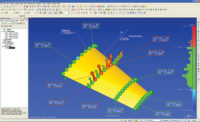
GD&T analysis is shown using industrial CT scanning software capabilities. Source: JG&A Metrology Center

Turning to industrial CT’s software capabilities for GD&T projects allows companies to obtain a complete and accurate 3-D model of the parts internal and external geometries. Source: JG&A Metrology Center


“GD&T was developed to address the many problems that had been encountered over the years as companies tried to describe their part geometry,” according to Bryan R. Fischer, president of Advanced Dimensional Management LLC.
“They realized that it was very difficult to quantify the variation allowed on the geometry of their parts and assemblies. More importantly, they found that everybody reading their drawings had a different interpretation of their specifications, and the limits they created. This led to mistakes, rejected parts, non-conforming parts, wasted time and money, and costly delays in production.
“Companies inevitably found that they had major difficulties describing the size and form limits of individual part and assembly features in a clear, concise manner. For example, often times it was not absolutely specified in the drawings how flat certain critical surfaces had to be. In other cases, the dimensions for the size, and the form requirements for a hole were vague at best.
“They also found that they had even greater difficulty describing how much variation was allowed between features. For example, it was very difficult to understand how much a hole was allowed to tilt relative to a surface, which surface it was allowed to tilt relative to, or how much variation was allowed between the related surfaces. GD&T was developed specifically to address these problems, in addition to eliminating the ambiguity that is inherent when using traditional plus/minus dimensioning and tolerancing. The primary purpose of GD&T is to make the drawing specifications clear and unambiguous. In turn, this will eliminate the problems, confusion, material scrap, rework, and loss of profits that results from using the archaic, traditional dimensioning method.”
When it comes to GD&T, measuring for internal features on component parts has proven to be difficult. Industrial CT scanning has become an integral part in GD&T and how the measurement of complex component parts should be facilitated. CT technology has seen massive improvements in their software analysis capabilities, allowing for an increase in accuracy when dealing with scanned datasets.
They purchased a tool that required the measurement of internal features and they wanted to check how close it was to the original specified print. The result: it was completely off.
GD&T through Industrial CT
Turning to industrial CT’s software capabilities (acc. to DIN EN ISO 1101) for your GD&T projects is a viable measurement solution for obtaining a complete and accurate 3-D model of the part’s internal and external geometries. Complex parts are scanned in a free-state environment, allowing for both external and internal components to be validated quickly and accurately without destructive testing. Once the scan is completed the GD&T program is written around the scan data set and referenced to the part print. From there, the GD&T program is instantaneously applied to future scans of the same or mirrored part.
Delivering critical insights into part features requires software that guarantees its accuracy. What you want is a successful scan, analysis and measurement of your part to make a qualified decision within a shorter time frame and get to production faster. This allows you to receive a value added solution because it increases the value in actionable data to drive performance improvement and it upgrades standards in quality control.
Working off a Gaussian least squares model, repeatability is much higher and measurement programs can be applied to multiple parts, so once a program is written it can be applied to subsequent parts as well. Since the software is a virtual environment, a coordinate system can be created however the user wants. With its intuitive menu and its approach of applying sub objects for measurement, the computed tomography software provides the ability to adjust a sub object, which is then updated down the chain. For example, cylindricity call outs are extremely difficult, time consuming, and costly to measure with alternative methods. The cylindricity function through industrial CT’s software with a CT dataset makes performance calculations as easy as finding a standard dimension or radii. Additional value added features of measuring GD&T through industrial CT software include:
- GD&T with CT datasets can be performed on parts less than 1 millimeter in size
- GD&T with CT datasets can be performed on small intricate parts in 3-D as opposed to 2-D
- GD&T with CT datasets can be performed on different material densities inside a part of an assembly
Industrial CT scanning works by taking several hundred to several thousands of 2-D X-ray images covering 360 degrees. Once the scan is completed the 2-D X-ray images are reconstructed in 3-D, giving you the opportunity to see the external and internal features of the part, inspect for defects, and capture exact geometrical measurements for comparison and metrology purposes.
GD&T has been an essential tool for establishing design intent, to make sure that parts meet the requirements of fit, function and interchangeability. Industrial CT scanning is setting a new standard in qualifying pre-production parts quickly and accurately while reducing inspection costs. This is achieved by using the right technology, expert analytical support, and scan data calibration to ensure accuracy. The accuracy, efficiency, and reduced turnaround time demonstrates that industrial CT scanning will continue its trend of becoming a required tool for inspection, as industry leaders are identifying both the value in inspection standards and the cost savings it offers.
This new functionality allows measurement uncertainty to be drastically reduced for all geometry based analysis, by rapid fitting of thousands of measuring points.
|
TECH TIPS
|
Looking for a reprint of this article?
From high-res PDFs to custom plaques, order your copy today!


