Measurement
Advances in Shaft Measurement
As shaft measurement systems have gained popularity, users have been demanding more and more capabilities from them.

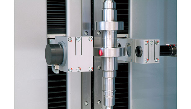
Demands for increased performance have drawn attention towards newer, fully automated optical shaft measuring systems. Such systems are designed to facilitate precision control of complex turned parts. Source: Mahr

Two technologies have commonly been used for these optical systems: line sensors and matrix cameras. Both use backlighting, i.e., silhouette imaging, which means the systems can’t “see” a feature inside a part, and thus can’t measure it. Source: Mahr

Figure 1. Line scan technology images part dimensions by means of a series of lines. In order to better measure edges and shoulders, the line sensors are often tipped slightly relative to the axis of the part. Source: Mahr

The important concept in a turbocharger is that the blades operate inside a housing: the tighter the clearance between the blades and the housing, the more efficient the turbocharger. Since each blade is slightly different, each reaches a slightly different maximum height when assembled on the wheel. Using a CCD matrix system and special application specific software, we were able to mount the shaft and wheel, rotate it, and define a best fit profile for the entire assembly. Feeding this data back to the machine tool, the manufacturer was able to optimize the process and maximize the efficiency of the turbocharger. Source: Mahr

The use of high-resolution matrix array, or CCD cameras, is more recent, and has been made possible by advances in computer processor technology. With systems such as this, many different measurements can be completed from a single image. Higher resolution makes measurements more stable and accurate, and allows measurement of much smaller features than the calculated image of a line scan. Source: Mahr


The term “shaft measurement system” is standard industry parlance today, but to think of these gages as measuring only shafts is too limiting. For the most part, anything created as a turned part on a lathe is probably well suited for these devices. If there are features such as diameters, lengths, groove widths, fillet radii or chamfers on the part then it is well suited for measurement by a shaft measurement system. For example, take the barrel or body of a fuel injector. It certainly would never be considered a “shaft.” Yet its outside dimensions have many turned features that have diameters that need to be controlled and a variety of grooves for O-rings that require very precise widths and depths. Shaft measuring systems are very good at measuring such features.
Shaft measurement systems have gained increasing popularity in recent years, and as a result users have been demanding more and more capabilities from them. They want them to run faster; they want to measure smaller features with tighter tolerances; they want their systems integrated to provide feedback directly to their machine tools; they want them easier to operate; and of course, they want them to be easier to use and more and more of the measurement process automated so all their operators have to do is “push a button.”
The Optical Trend
These demands for increased performance have drawn attention away from other means of shaft measurement, such as CMMs and purpose-built manual systems (even though such systems continue to perform well in their applications) and towards newer, fully automated optical shaft measuring systems. Such systems are designed to facilitate precision control of complex turned parts. Able to operate both in the lab and on the shop floor, they allow the measurement of many characteristics on turned parts in seconds and without contact. Fully automatic measuring sequences eliminate operator influence from measurement results, and in many systems graphic interfaces simplify programming and use.
Two technologies have commonly been used for these optical systems: line sensors and matrix cameras. Both use backlighting, i.e., silhouette imaging, which means the systems can’t “see” a feature inside a part, and thus can’t measure it. But beyond that, there are other advantages and disadvantages that need to be considered.
Line scan technology is very fast and has been used in the field for more than twenty years. As its name implies, line scan technology images part dimensions by means of a series of lines, a single line at a time. In order to better measure edges and shoulders, the line sensors are often tipped slightly relative to the axis of the part. Part and feature diameters are indicated as a series of connected points or dots, and measurement computations are made with this “calculated” image of the part. Because of this lower resolution, small features are harder to measure.
The use of high-resolution matrix array, or CCD cameras, is somewhat newer and has seen more recent advances with leaps in computer processor speed. While faster than other measurement methods, matrix measurements have historically been slightly slower than line sensors due to the larger amount of data to be processed. However, faster processors and measurement optimization programs are narrowing, and in many cases, eliminating that gap. Higher resolution makes measurements more stable and accurate, and allows measurement of much smaller features than the calculated image of a line scan. The best matrix systems virtually eliminate all operator influence, and to ensure the highest possible accuracy, take multiple images per measurement.
Matrix Gaining the Lead
A recent case where the dramatic difference between the two technologies was quite evident involved a turbocharger shaft with impeller wheel. The blade on the impeller wheel had a very complex profile. Some of the edges were almost horizontal. Thus, if you used a horizontal line scan camera some of the scan would be on the edge, but the rest would be either above or below the edge where you couldn’t see anything. You wouldn’t know where that edge was between your scan lines or what the actual transition of the shape looked like. With a line scan camera you would have to go back and scan with finer and finer increments to see what that looked like. With a CCD matrix camera you don’t have to do that: you see the whole profile. The matrix camera measurement capability was dramatically superior to the line scan camera results for these types of features.
The important concept in a turbocharger is that the blades operate inside a housing: the tighter the clearance between the blades and the housing, the more efficient the turbocharger. Since each blade is slightly different, each reaches a slightly different maximum height when assembled on the wheel. However, using a CCD matrix system and special application specific software, we were able to mount the shaft and wheel, rotate it, and define a best fit profile for the entire assembly. Feeding this data back to the machine tool, the manufacturer was able to optimize the process and maximize the efficiency of the turbocharger.
Improved Speed and Accuracy
There have been a number of other significant advances in matrix-based systems of late. Speed, for example, has been increased by several means. First, of course, processors are faster, as are the controllers that run them, so processing time is less. You can see this quite easily in watching newer generation systems. Where you used to see the machines move, capture an image and then pause for a split second to calculate something before it moved on to the next point, now they move so quickly there are no discernible pauses. Processing time has become inconsequential.
Newer systems are also using optimization routines to speed up the measuring process in a couple of ways. When programming older systems, you first moved the machine to a certain place where it would take a picture. Then you would define area, or region, of interest (AOI or ROI) within the picture where you expected to find an edge or a radius or other feature. You would repeat this process for each feature to be measured, and when the program ran, it would move to each pre-determined spot, take an image, and analyze the data within each AOI to determine the results.
With the latest systems, when you finish programming, the first thing the system does is run an optimization program that looks at your AOIs and says, for example, “Okay, you have these three AOIs that are pretty close together. Can I move to a location such that I can get them all in one camera image?” So where an older system would have taken three images, newer systems offer the possibility of doing the same thing with one image. These systems will also optimize the movement in between image captures to cover the minimum distances between these locations.
Accuracy has also improved. Manufacturers keep making strides in system designs and every new gage is more accurate than its predecessor. Newer systems are using components from other higher-end form measuring systems. Some of those systems are capable of sub-micron measurements so the shaft measuring systems benefit greatly from this technology. Uncertainty statements continue to improve with each new generation of systems.
Of course, every year the machine tool industry also makes improvements in what tolerances their turning machines can achieve, so it is a constant race to get ahead of the curve.
Integrated Operating Platforms
Leading matrix-based shaft measurement systems already do a pretty good job providing feedback and integrating with machine tools and manufacturing systems in their environments. But some shaft measurement system manufacturers are also integrating their gages into new metrology platforms with “smart interface” operating systems that promise even easier operation, better performance and faster customization than ever before.
The concept here is to implement the idea of modularization on an operating system level. If all the metrology systems in a manufacturer’s facility operate in the same way, using the same basic command and interface structure, then any number of benefits can accrue, both for the manufacturer and the gage maker. For one thing, not so much time has to be spent writing and updating system software. And since every gage in a line uses the same basic operator interface, users can more easily operate different types of gages: whether they are making a surface roughness, form or shaft measurement, the gage setup looks basically the same and they go through the same basic steps to operate it.
In addition, because different gaging systems operate on the same platform, “cross-pollination” is possible between gages: surface and contour measurements can now be taken on a form machine; form measurements can be taken on surface machines; and soon both may be able to be taken on shaft measurement systems. This promises to dramatically enhance the entire dimensional measurement process. Customization for specialized applications is simplified by this common platform. With all of the tools and software libraries from all the different types of gages available, the ability to create application or customer specific solutions is greatly enhanced. And because all systems in a manufacturer’s line operate the same way, operator training is minimized and ease-of-use is maximized.
But it is still early days for this level of integration. The process is still evolving and new possibilities emerging almost daily.
TECH TIPS
|
Looking for a reprint of this article?
From high-res PDFs to custom plaques, order your copy today!


