Test & Inspection
A Turn for the Better: Advances in Multisensor Systems
Multisensor systems allow complex parts to be easily measured in one setup using the best sensor for each measurement situation.


Figure 1: Rotary indexer mounted on a three-axis multisensor measuring system. Source: OGP

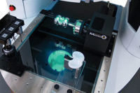
Figure 2: Micro-Theta rotary indexer offers high resolution rotational positioning. Source: OGP

Figure 3: High-precision rotary indexer mounted on a 45-degree incline fixture. Source: OGP

Figure 4: Standard Coordinate Reference Frame Rotated. Source: OGP

Figure 5: Part on Rotary Coordinate Reference Frame. Source: OGP

Figure 6: Turbine blade measured using continuous contact scanning with rotation. Source: OGP

Figure 7: General arrangement of a compound rotary indexer. Source: OGP

Figure 8: Dual heavy-duty rotary indexers in a compound arrangement for turbine blade measurement. Source: OGP


Multisensor metrology systems have evolved over the past 20 years to integrate a wide array of sensor techniques—optical, laser, touch-probe, white light and scanning probe—into highly accurate three-axis coordinate measuring machines. Advanced measuring software allows all sensors to remain simultaneously calibrated and available for deployment at any step in a measurement routine. Multisensor systems allow complex parts to be easily measured in one setup using the best sensor for each measurement situation.
The only significant limitation on using the full array of sensors has been that deployment was limited to the standard three-axes of motion (X, Y and Z) of the measuring machine. Something as simple as inspecting both sides of a part required the part to be removed and re-fixtured for measurement of the second side. More complex measurements, such as relationships between features on different surfaces were sometimes impossible to make using a three-axis measuring system.
Today, advancements in software, calibration techniques and fixture tooling have made it practical to add 4th or 5th axis rotary motion to three-axis multisensor systems, enabling complete inspections of many turned, shaped or rounded parts in a single setup. With the right hardware and software, multisensor measurement can now be extended to define complete 3-D relationships of features that lie on multiple faces of a work piece.
Adding rotary motion to a measuring machine is not as simple as using any off-the-shelf rotary device. Traditional rotary devices have a number of drawbacks. They tend to be heavy, difficult to install and remove, and take up valuable space in the measurement envelope, limiting the measuring range available for the part at hand. Many were manually actuated, and ones that were automatic often lacked sophisticated theta position feedback, making it difficult to repeat critical positioning setups.
TECH TIPS
|
Today’s rotary stages take advantage of more compact design and on-board electronics that add a great deal of utility. Smaller rotary packages take up less of the valuable measuring envelope while still offering the load capacity and torque needed to index payloads smoothly. The latest micro-motors and on-board electronics allow accurate position feedback at all times—even without an “initialize” sequence requiring full 360-degree rotation to confirm index positions.
Fixture tooling can also enable easier installation and removal of a rotary device, so that it can be easily removed when not needed, but also easily re-installed. Tapped holes or dovetail slots in the X,Y measuring stage enable accurate positioning of the rotary in the machine’s measuring volume. A significant concern when mounting a rotary device is the routing of control and power cables. Cable drag can have a significant impact on both linear and rotary motion accuracy, so it’s important to provide an effective means of dressing cables for any fixture tooling. Figure 2 shows a rotary device mounted on an X,Y stage with built-in electrical connections for an auxiliary device, enabling the entire rotary control cable to reside on-board the moving axis.
On-board electronics play an equally important role to the mechanics in terms of improved rotary performance. Today’s scales and reader heads are compact and highly accurate, enabling better performance. They are also capable of very high resolution.
Figure 2 shows a device with a high resolution scale and dual reader heads for closed loop angular positioning. This device has a high resolution encoder with 1,400,000 counts per revolution, enabling positional resolution to less than two arc seconds. This type of feedback system allows the software to interpret the rotational position of the rotary faceplate at all times without having to index through a full revolution. This can be an important consideration when it is not possible to rotate a fixtured part through a full 360 degree rotation.
Another traditional limitation with rotary stages—or any special fixture tooling—is that they needed to be calibrated at a single position on the measuring machine. Removing and replacing the fixture involved a complex and time-consuming calibration before measurement could resume. Today’s software allows fixtures, including rotary stages, to be easily calibrated at any position, elevation or azimuth. This opens up several possibilities for using a rotary device that make it practical to “gun-barrel” a part so that the features of interest can be viewed and measured optically no matter their orientations.
Figure 3 shows an example: a high precision air-bearing rotary device is mounted on a 45-degree incline fixture to enable the nozzles of fuel injectors to be measured using a combination of optics and microprobe. Without the ability to calibrate the rotary stage arbitrarily positioned in 3-D space, it would not be practical to measure the critical dimensions on this part in a single setup.
Fourth and 5th axis rotary devices have many applications in key manufacturing fields such as aerospace, automotive and medical devices. The critical requirement in all cases is the ability of the measuring software to rotate the part’s coordinate reference system in 3-D space as the part is rotated to maintain datum integrity. Using conventional software, this can be done by measuring the same set of datum reference features in each rotary position. In this way the part’s datum reference frame can be re-established each time the part is rotated. When the same set of datum features cannot be re-measured in a new orientation, then a substitute set of features, such as tooling balls, pins or gage blocks attached to the part or rotary faceplate can be used to re-set datums. This is the tedious process required to make relational angle measurements using most dimensional measurement software.
Using advanced 3-D measurement software, it is possible to translate the part’s coordinate reference system with the part as it is indexed on the rotary axis. Figures 4 and 5 show the transformations of a three-axis coordinate reference frame as the part is rotated about its axis. This is the true Part on Rotary application that enables full four or five axis measurement.
Advanced metrology software offers a variety of features to facilitate measurement set-up and system operation when using the Part on Rotary feature. For example, some systems allow manual movement of the X,Y,Z stages using a handheld joystick controller. When the Part on Rotary feature is in use, joystick motion can be linked to the part’s On-Rotary coordinate reference frame, so that manual stage motion mimics the part’s datum reference frame. Advanced software also calculates appropriate vector approaches for tactile probes, reducing unnecessary stage motion and ensuring safe operation when a part is rotated in 3-D space.
Medical devices present some of the most challenging measurement requirements of any class of parts. Implantable orthopedic devices such as hips, knees and joints have complex profiles which are not easily broken down and measured as conventional geometries.
The knee joint in Figure 2, for example, is a compound curve with a profile tolerance unconstrained by any datums. To measure the entire curve and fit the data to the CAD profile requires both a laser and scanning probe, and the ability to rotate the part through more than 120 degrees of arc to cross-section the part in the required locations. A micro theta rotary stage enables this exact combination of sensors and rotation, allowing the entire part to measured in a single setup, without the need to re-fixture.
The turbine blade shown in Figure 6 requires measurement of form and size and position of slots. Rotation enables the entire form to be measured using the SP-25 scanning probe. A unique new software routine enables continuous scanning while rotating, with a feedback loop to the SP-25 to keep the probe in constant contact with the blade while simultaneously moving X, Y, Z and theta axes. This technique improves throughput by more than 25%, and enables all measurements to be completed in a single setup.
Some applications require combining 4th and 5th axes to completely characterize a part with features on three or more separate surfaces. In this case, mounting two rotary indexers together with their axes perpendicular to one another allows a part to be mounted to the secondary rotary, which is attached to the primary rotary. The part can be rotated about two different axes to bring features with compound angles into the line of sight of the optical axis, or within easy reach of available laser sensors or touch probes.
This “compound rotary” is often used for inspection of cooling holes in aircraft engine turbine blades and vanes. The primary rotary devices used in this setup must be heavy-duty, with high load carrying capacity and plenty of torque for good position holding. The secondary rotary stage may be a smaller unit, with high resolution and fine positioning capability to accurately gun-barrel each cooling hole so it can be measured by the system optics. This setup does consume a substantial part of the measuring volume, particularly in the Z-axis, and therefore requires a measuring platform with substantial Z-axis measuring range and working clearance.
State of the art rotary indexer technology and advanced metrology software have opened the door to using multisensor systems to measure a much wider range of parts and 3-D geometries in a single part setup. Fully automated control of single and dual rotary devices with true Part on Rotary software functionality is allowing complete verification of complex dimensions of manufactured parts. New technologies such as additive manufacturing are enabling the production of even more complex part geometries. Future systems will need to embrace even more complex work piece positioning functionality including eight or more axes of motion to reposition not only the work piece but also the array of measurement sensors on the machine.
Looking for a reprint of this article?
From high-res PDFs to custom plaques, order your copy today!


