Measurement
How to Choose the Right Lighting for Machine Vision Applications
“The most sophisticated automated inspection system in the world cannot work without the proper lighting.”

Figure 1. High contrast helps a vision system provide more repeatable results. Source: Cognex Corporation

Figure 2. IR light through a filter highlights bruises on fruit. Source: Cognex Corporation

Figure 3. Collimated light rays create sharper images. Source: Cognex Corporation

Figure 4a. Light Bulb with direct illumination from a ring light. The ring light is reflected in the glass. Source: Cognex Corporation

Figure 4b. Back-lighted light bulb. Using a back light. All the glare is avoided and the internal features can be inspected clearly. Source: Cognex Corporation

Figure 5a. A sponge illuminated by direct lighting with a high angle of incidence. Source: Cognex Corporation

Figure 5b. By shifting the position of the light source, glare is reduced and the surface texture of the sponge is exposed for inspection. Source: Cognex Corporation

Figure 6a. A line light, reflecting off of a completely flat surface will appear perfectly straight. Source: Cognex Corporation

Figure 6b. If the surface is not perfectly flat, the reflection produced by the light bouncing off of the surface will not be perfectly straight. In this case, there is a depression in the surface. Source: Cognex Corporation

Figure 7a. A dot matrix code viewed in ambient direct light coming from one side. Source: Cognex Corporation

Figure 7b. The same dot matrix code viewed with diffuse on-axis lighting (DOAL). Source: Cognex Corporation

Figure 8a. A beverage can illuminated by direct lighting, in this case a ring light, reflects glare to the camera. Source: Cognex Corporation

Figure 8b. The same can illuminated by diffuse off-axis lighting provides a clear image of surface markings. Source: Cognex Corporation

Figure 9a. Image taken of a moving part using strobe light illumination. Source: Cognex Corporation

Figure 9b. Image taken of a moving part using continuous illumination. Source: Cognex Corporation

How Light Stacks Up. Source: Cognex Corporation


Machine vision systems create images by analyzing the reflected light from an object, not by analyzing the object itself. Therefore it is critical to understand how light will reflect from a production part that one is inspecting. To understand this, one must understand the material that the object is made from, its size, shape, and finish. The object’s color is also important, even if the inspection system is monochromatic (a red part will reflect differently from a pink part). All of these characteristics affect how light is reflected, and may pose challenges in creating a good image. Finding the right light source can take a seemingly difficult application and simplify it.
Lighting can also affect how easy it is for computer analysis to produce a workable image. A good image is the result of proper focus and illumination. Images with poor contrast and uneven illumination require much more effort for the imaging computer, which ultimately increases the processing time, and can increase the number of incorrect image analyses. Generally, high contrast images are the easiest to process. Consider the image below (Figure 1). A good image processing system is capable of recognizing the plus signs in both images, however the repeatability of recognizing the top image will be lower due to the low contrast of this image compared to the one on the bottom. If illumination is properly controlled, the images should be handled by the machine vision system easily and with a high degree of reliability/repeatability.
Since images are created when light reflects off of an object, light that strikes the object and is reflected towards the camera is seen as being bright. If light is reflected away from the camera (or is absorbed by the object), the object is seen as being dark. A machine vision system typically focuses on the differences between light and dark areas to make conclusions about edges, textures or markings that are critical parameters in the inspection operation.
Types of Lighting
The wavelength of the light that is used can also be an important variable in the inspection process. With illumination by light of a particular color, contrasting colors will be easier to separate out because they will appear dark in the image. This technique can be used to enhance the date codes on jar lids, for example.
Infrared light can be used to highlight bruises on produce, and ultra violet light will cause ink or glue to fluoresce (note that filters should be used on the camera if infrared or ultraviolet light are being used so that the fluorescence of the object can be viewed but not the light itself).
Collimated light, where the light rays are aligned so as to always be parallel, is good for producing sharp images.
Diffused light, which can be produced by taking collimated light and shining it through frosted glass, gives a softer, more even illumination which avoids causing glare or shadows at the cost of reducing the light’s intensity.
Another consideration when inspecting parts is the speed of motion of the part as it is photographed, as well as the exposure time of the camera. These factors will affect the choice of light source.
Simplifying the application starts with defining the goals and focusing on what is important to the inspection. Once the goals are understood, one can then focus on choosing the light source that highlights the features or defects that are being looked-for and cancels out the unwanted elements of the image.
Lighting Techniques
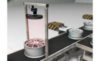
Selecting the correct lighting technique can go a long way in dealing with the special issues of a particular application. Many options are available, and each has pros and cons for specific uses. There are five basic techniques for lighting parts to be inspected: Back lighting, direct lighting, structured lighting, and on- or off-axis diffuse lighting.
Back lighting creates a silhouette to accentuate the shape of a part and allow for its measurement, but totally obscures all surface detail. It creates the maximum amount of contrast by producing an image that is for the most part black on white. Inspection applications can use this technique for making dimensional measurements, but it would be useless for surface inspection. A challenge to this technique is the difficulty in fixturing. Any mechanical fixture that must hold the part being inspected could obstruct the back light. Consider the following example.
The second lighting technique is direct front lighting. Typically, the light is illuminating from a slightly off-center angle. It is easy to set up such a lighting source and it can create excellent contrast, however it can also create shadows, and may produce glare depending on the surface of the part being inspected. Creating shadows may be desirable, to enhance contrast where low-contrast images are a problem. And, direct lighting may be used to freeze motion with strobes. For an example of the effect of moving the light source, consider the following images.
If shadows are to be minimized, more than one direct light can be used. For this purpose, some systems use a ring light, which totally surrounds the part being viewed.
Another lighting technique is structured lighting. Structured lighting makes use of a known light pattern (normally a plane of light creating a line) that is used to obtain dimensional information. Typically highly-collimated light sources are used, such as lasers or fiber optic line lights. This technique is an inexpensive way to measure depth and height of continuous surfaces and is often used when either the light source or the surface are moving. It can also show surface details on low-contrast parts. One should make sure that the part being measured does not absorb light, however, since reflection is required for the lighting’s effect on the part to be measured. The effect of a linear light source being reflected off of perfectly flat and non-continuous surfaces is shown in Figures 4a and 4b.
Diffuse on-axis lighting, also known as DOAL, allows for light to be shone directly at a part in line with the camera, without the light source getting in the way of the camera. This is accomplished using a 50% silvered mirror to reflect light directly at the part. The camera sees through the mirror to capture the image of the part being illuminated.
Diffuse, on-axis lighting applications include detecting flaws on shiny, flat surfaces or inspecting the insides of small cavities. Since DOAL lights lose intensity through the silvered mirror, it may be advisable to use an additional lighting source to improve the illumination or the consistency of light on the subject.
Figures 5a and 5b show how using DOAL can eliminate reflected glare, making it easier to inspect surface features in some applications.
The last lighting technique explained here is diffuse off-axis lighting, also known as cloudy day lighting or dome light illumination. With this technique, the light is not reflected directly onto the part, but first onto a diffuse surface and then it is “bounced” onto the part.
The diffused off-axis technique negates shadows as if one was looking at something on a cloudy day. It also avoids creating hot spots or glare that can cause problems in parts inspection applications. When a dome light is used, where the camera shoots through a hole in the reflector dome, there can be a dead spot in the center of the image. Therefore, when a reflector is used, it may be advantageous to add a DOAL source to fill in the dead spot.
For applications that are space-constrained, flat dome lights are available to place between the camera and the part and which produce similar results to curved ones.
Always-on or Strobed
Lighting in machine vision applications is either always-on or strobed. By strobing a light one can get increased intensity, and the light source may last longer. More useful is the ability to stop motion. But, strobes need to be controlled. The timing must be precisely coordinated with image acquisition, or the images will vary in intensity. There is also the human factor to consider when using strobe lighting. Flashing lights can cause seizures or headaches when viewed by some people.
In designing machine vision systems, it is important to consider the affect of ambient light in the area where the machine is to be installed. The light used to illuminate the part needs to be bright enough to overwhelm any ambient light that shines on it so that the intended effect of the inspection system’s special illumination is accomplished. Ambient light can cause additional glare on parts. It can also change depending on where the operator may be standing, the time of day, the weather, and season of the year. All these issues need to be considered when selecting the inspection system’s light source and designing the machine’s physical layout.
Lighting Sources
One type of light source is halogen lights. These are good for applications where very bright lighting is required—many new automobile headlights are halogen—but they are limited in the fact that they cannot be strobed, they tend to run very hot, and they lose intensity over time. If this type of light is to be used for an inspection application, it would be beneficial to run it at 80% of its maximum power to extend its life, keeping the voltage constant to avoid color changes, and using fiber optics to enable mounting the lamp remotely if the application is sensitive to the halogen heat produced.
Incandescent lights are another possible source. These light bulbs are inexpensive and readily available, but they can’t be strobed, they generate heat, and they lose intensity slightly over time.
Fluorescent lighting sources are relatively inexpensive. They are available in many shapes and sizes, and provide diffuse light, minimizing glare. The limiting factors here are that they can’t be strobed, they degrade over time, and it’s difficult to dim them. Fluorescent lights also flicker due to the frequency of the AC power source, which can affect the image quality of vision inspection applications. Using high frequency ballasts can help reduce the amount of flicker, but can’t eliminate it entirely.
Lasers are highly collimated light sources which have high intensity, allowing them to be mounted a distance from the object being inspected. A special type of laser, called a diode laser, can be strobed. Lasers are often used to make distance measurements, sometimes in three dimensions, but may not be capable of high accuracies. Lasers are traditionally very expensive and require special safety precautions as they present potential safety hazards. Fiber optics may provide a safer option to provide collimated light if one’s application requires it.
Many older strobing systems employ Xenon lights. Xenon is ideal for strobing because it is capable of giving very high intensity over a short period of time, thus creating the impression of stopped motion. But the intensity of Xenon strobes decreases over time and they are rarely used today.
A better alternative is to use light emitting diodes, LEDs. These sources are the most common ones for machine vision applications today. They last a very long time, in excess of 10,000 hours, and they can be strobed or left on continuously without heat issues. LEDs are also very safe to use, they are efficient, and you can source them in virtually any color or specific wavelength. While early LEDs had limited intensity, modern LEDs can be very bright (consider how many new cars are using them for exterior lighting).
The following chart compares the different light source alternatives as to their suitability for different applications:
Summary
There are many lighting options available and many different ways to construct and orient the vision system. Choosing the right lighting can make a significant difference in the productivity of one’s machine. The first thing that must be done when planning a new automated inspection system is to understand the part that is to be inspected – what needs to be learned by inspecting it, its surface finish, its color, etc. It’s also critical to understand the production environment. Then, review the pros and cons of various light sources. After selecting the right lighting, the next decision is to position the light source for maximum effectiveness. The combination of the lighting source and how it is placed respective to the part and the camera can negate or accentuate features as appropriate to ensure that good, consistent images are produced to meet the inspection requirements of the application.
Looking for a reprint of this article?
From high-res PDFs to custom plaques, order your copy today!


