Software & Analysis
Modern Reverse Engineering of 3-D Geometry
The purposes for reverse engineering are many and varied, ranging from the need to reproduce an existing product lacking CAD documentation to acquiring sensitive information to determine possible patent infringement


Many ideas can spring to mind when one hears the term reverse engineering. Some think of it as a form of corporate espionage, a means to copy competitors’ parts, others regard it primarily in terms of their own immediate industrial needs, as in the case of an electronics manufacturer using reverse engineering to replicate printed circuit boards (PCBs). However, the purposes for reverse engineering are many and varied, ranging from the need to reproduce an existing product lacking CAD documentation, which we discuss later, to acquiring sensitive information to determine possible patent infringement.
One of the earliest, and darker, cases of reverse engineering took place during World War II. Following the attack on Pearl Harbor, which cost the lives of 2,400 servicemen, the U.S. was determined to strike back at Japan, whose growing militarism had posed a grave threat to countries throughout the Pacific Rim since the 1930s. One of the weapons designated for use against Japan was the Boeing B-29 Superfortress heavy bomber, then under development. However, the Superfortress was a long-range bomber and needed a place to land and refuel. Joseph Stalin granted permission for Superfortress crews to use the city of Vladivostok in eastern-most Russia as a base for refueling. Three B-29s landed in the Russian city and were never seen again. Five years later the Russians introduced their Tupolev Tu-4 aircraft, which looked nearly identical to the B-29 Superfortress.
A large and growing field of reverse engineering is fueled by the need for companies to reproduce their own parts for which there are no CAD models or 2-D drawings. The part may have been designed in a pre-CAD era and/or the 2-D documentation was lost. Or perhaps the suppliers that originally built the equipment are no longer in business. There are even times when models or prints exist but the component was modified over the years to a point it no longer resembles the drawings. In all of these scenarios, it becomes essential to obtain the exact geometry of the existing part so that a 3-D CAD model can be created.
When parts are simple shapes, calipers and other hand tools can be used to measure the dimensions. However, as parts become more complex, non-contact scanning methods are far superior in their ability to fully capture all features and dimensions accurately and with greater resolution.
The three phases of reverse engineering are data collection, data processing, and data modeling.
Data Collection by 3-D Scanning
Portable CMM Scanners: A coordinate measuring machine, or CMM, is a non-contact scanning device that uses a laser line triangulation sensor on the CMM to capture an object’s 3-D coordinates, or data points, rapidly and with a high degree of resolution and accuracy. One advantage of this type of scanning is its versatility. It’s capable of capturing 3-D geometry from objects of various sizes and shapes, in almost any environment. The flexibility, speed, ease of use, and portability make it a suitable choice for nearly every type of reverse engineering application, from consumer goods to full-size automobiles.
Optical CMM scanning: Optical CMMs are capable of obtaining extremely accurate scan data, largely because they utilize high precision linear encoders. These systems are ideal for applications requiring extremely high accuracy such as turbine blades, injection molds, test equipment, and master gages where accuracy needs to be greater than 0.001 inch or 0.025 millimeter.
Computed Tomography (CT) scanning is one of the most accurate and high-resolution scanning technologies available for reverse engineering. CT scanning utilizes X-rays to produce 3-D representations of both internal and external surfaces. It is fast, accurate, non-invasive and nondestructive. Its ability to capture internal geometry makes CT scanning a good choice when measurement requirements exceed the capabilities of line of sight scanning technology.
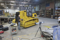
Long-range scanning: This process is used when large-scale data capture is needed. For example, when you need the as-built data about structures such as factories, power plants, and oil platforms; construction projects such as road or bridges; or industrial machinery and equipment. Among its other benefits, it allows early detection of interferences and design flaws and can be used to create blueprints and floor plans.
Structured Light Scanners use white or blue light to create a series of reference patterns on an object. The light deflects onto the object’s surface. The scanner captures these images to calculate the object’s depth and surface information. To stitch together multiple scans, reference stickers are often used or photogrammetry is employed.
TECH TIPSA large and growing field of reverse engineering is fueled by the need for companies to reproduce their own parts for which there are no CAD models or 2-D drawings. There are even times when models or prints exist but the component was modified over the years to a point it no longer resembles the drawings. In these scenarios, it becomes essential to obtain the exact geometry of the existing part so that a 3-D CAD model can be created. |
Data Processing of Point Clouds
Once the data collection, or scanning, portion of a project is complete, what you will generally have is a “cloud” of points, consisting of perhaps millions of XYZ and IJK co-ordinates. Possibly there will be data collected from a number of locations, or views, which need to be integrated into a single co-ordinate system (i.e. with common zero position). Before this data can be easily used for reverse engineering or inspection, it is generally converted into a triangulated STL polygonal file.
The first stage is to combine multiple data sets into one. This may be accomplished by using datum entities picked up during scanning or created from the data, or by using best fit algorithms to align the data sets to each other.
The data collected will consist of a number of overlapping “patches.” This must be reduced to a single layer or “one point thickness” of data, with the overlapping data being processed for noise reduction, and possibly filtered. Depending on the software, this may be carried out using either a volumetric or a patch-based algorithm to create a triangulated data set at a point spacing predefined by the operator.
The STL file may be further processed by decimating the data to reduce the number of triangles using a 3-D tolerance, smoothing of the data to reduce the inevitable “noise” produced by system inaccuracies, and hole filling.
Before handing the data off to the next stage, the data will also be aligned to a co-ordinate system defined either by the customer, or one that is applicable to the part either individually or to its place in an assembly.
Data Modeling
The resulting STL polygonal model is used as a template for processing. Commercial software specialized in handling large STL files will process the data to a finished model format for manufacturing purposes.
Native CAD models are constructed from the STL data by using standard tools such as extrudes, lofts, sweeps, and revolves. For more difficult components, advanced surfacing techniques may be needed to achieve the desired result. Each model made is fully parametric and can be changed as desired in any step of the process. An accuracy analyzer is employed to give a color map of how close the model is to the STL template.
Most applications will require either a “dumb” solid model or a native CAD model. A “dumb” solid is a solid model without a history tree and the most common formats are IGES, STEP, or ParaSolid. When an application requires an exact duplication of an existing physical part then a dump solid will normally suffice.
With its ability to capture the precise physical geometry of a component and then create a CAD file of the part, 3-D scanning and specialized reverse engineering software are key technologies available to engineers tasked with obsolescence management.
Looking for a reprint of this article?
From high-res PDFs to custom plaques, order your copy today!


