Inspection of 60 Degrees Working Thread Plug Gages


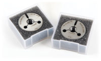
Working thread plug gages are the fixed limit functional gages used to inspect product threads on a pass/fail basis. If the go fits and the no-go does not, your parts are in tolerance. The function of the gages is straightforward. However, how do we know our thread plug gages are in tolerance? We inspect, measure or calibrate them. These three terms can mean different things to different people. For our purposes we will use “inspect” to mean visual inspection for damage and foreign material. “Measure” will be an actual measurement of a specific feature. “Calibration” incorporates the other two and includes the recorded measurements taken in a controlled environment with stated uncertainties in an accredited lab.
60 Degree Thread Measuring WiresMeasuring Pitch Diameter by the Three Wire Method. Tolerance: .000020" Sets Matched w/in .000010" Material: Tool Steel 59/64 Rc ANSI/ASME B89.1.17 Catalog pg.# 82-84 The selection of thread measuring wires is based on either the threads per inch or thread pitch. Source: Vermont Gage |
Step 1:
Clean the thread plug gage. This cleaning may use oils, solvents, forced air, ultrasonic or other methods. The key here is to remove as much foreign material as possible from the gage. The use of solvents like mineral spirits or alcohol will strip steel gages of their protective oils. This then exposes the gages to potential corrosion if not handled correctly. You may also use a soft bristle brush to remove the more stubborn materials. Be sure to re-oil the gages immediately after inspection.
Step 2:
Inspect the gage for visual damage, debris or corrosion. Visual damage may be as obvious as broken or chipped threads or as minimal as a discoloration or foreign material from a previous machining operation. If damage is found, replace the gage. If other visual issues are noted, repeat step 1.
Step 3:
Measure the attributes independently. ANSI ASME B1.2, Table 13, defines these attributes as “lead, flank angles, major diameter, pitch diameter, taper, straightness, roundness, and clearance at root.” Of these attributes, the pitch diameter is the most commonly measured.
The measurement of the pitch diameter / groove diameter is widely viewed as the most critical measurement. Gage major and minor diameters are calculated based on the supplied pitch diameters, see ASME B1.2, ”Gages and Gaging for Unified Inch Screw Threads.” The most common method for measuring pitch diameter is a measurement over wires using thread measuring wires per ASME B89.1.17, “Measurement of Thread Measuring Wires.” This is also called the “Three Wire Method.”
This measurement system has three key components. They are the measuring device, calibrated gage blocks and the thread measuring wires. All are critical to the accuracy of the final measured value.
The measuring device will need an accuracy of .000010” (0.0002mm) or better with an adjustable measuring force. You will also need calibrated gage blocks to set the measuring device. The thread measuring wires are an area where this measurement can become challenging. Using the wrong best wire diameter, wire constant, measuring pressure or wire holding device will be detrimental to the accuracy of the measurement.
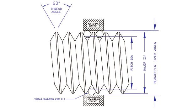
The selection of thread measuring wires is based on either the threads per inch or thread pitch. A ¼-20 UNC 2B Go plug gage is measured with 20 TPI wires. Thread measuring wires are manufactured as a matched set of three wires per ASME B89.1.17. Each wire diameter is matched to the others within .000010”. The diameters of the three wires shall be within .000020” of the calculated best wire diameter. Thread measuring wires are used to measure the “simple pitch diameter” of the external thread. This measurement is performed by placing the wires into the thread groove and against the anvil of the measuring device. Two wires are placed on one side and the third wire is placed on the opposite side, 180° from the two wires. (See the illustration on this page.) This setup can be difficult when dealing with fine pitch threads. Eighty TPI threads have a best wire size of .007217”. A typical human hair is .003”. Handling steel wires of this size can be challenging.
If you lose one wire, the entire set of three needs to be replaced. To make this process a little easier, thread measuring wire holders have been developed that slip over the anvils and hold the wires in place as anvil pressure is applied. Regardless how you hold the wires in the groove and against the anvils, it is critical that the wires are allowed to float freely in the thread groove. If you are using holders, be sure that the holder is floating freely on the measuring device anvils. Once properly seated, be sure that the measuring pressure on the measuring device is set to the correct pressure per ASME B89.1.17. The measuring pressure is used to align the wire in the groove. Using the specified force also helps to eliminate inconsistencies in the measurement and control the deformation of the wires.
Once these steps are complete, you are ready to take a measurement. The measure you will take is the measured diameter over wires (MOW or DOW). From this MOW, you will subtract the “C” constant. The constant is the calculated dimension from the point where the wires contact the flanks of the thread to the top of the wires (MOW – C = Measured PD). The original constant, calculated from the average of the actual measured wire diameters, will be stated on the container for all 60° thread measuring wires. Be careful, high helix threads such as multiple start threads and threads other than 60° thread form will require re-calculation of the constant to allow for any lead angle corrections. These corrections are required to ensure that your measurements are accurate.
Pitch diameter measurement alone does not mean the gage is in tolerance. The other attributes need to be measured as well. Be sure to refer to the applicable industry or governing standard for further information.
Looking for a reprint of this article?
From high-res PDFs to custom plaques, order your copy today!


