Form 101
Size matters, but being in shape often matters more.


While John Goodman and Arnold Schwarzenegger are both 6’2”, few would argue that they have similar body shapes. What this says, simply, is that measuring size does not necessarily say anything about shape. Even if you added other size dimensions, such as weight, shoe size, inseam length and hat size, you would still not know much about their relative shapes. Add waistline and you would start to get a sense of the difference, but from a manufacturing (or sculpting) perspective, you would still not have nearly enough information to produce either shape, or to differentiate between them.
A simple example of this in the dimensional metrology world is shown in Figure 1, where a series of two-point diameter measurements attempt to indicate roundness. While all the measurements show a nominal diameter of 1.0”, they mask various lobed conditions on the parts, which indicate actual IDs as small as 0.844” and ODs as large as 1.155”.
This is why we need to measure form when manufacturing precision components. In fact, there are a lot of applications where the shape of a part is actually more important than its size. A shaft that fits into a hole, for example, may need to be very round, but the amount of clearance around it may not be as critical. So the dimensional tolerance may be larger than the roundness tolerance.
This is why GD&T (Geometric Dimensioning and Tolerancing) was originally developed. It provides the means to define and communicate the geometric requirements for precision parts and assemblies. Form tolerances used in addition to traditional dimensional tolerances provide a refinement of the size tolerance for the desired shape. A form tolerance is normally smaller than the size tolerance it is used with. Take for example the round shaft. If the roundness tolerance is larger than the diameter tolerance, then it doesn’t serve any purpose, because the diameter tolerance already controls the worst shape possible since all parts of the surface need to be within the size tolerance.
GD&T allows for a variety of form tolerances that help to control the basic shape of a surface. The allowable tolerances are roundness and straightness for 2-D control of a surface, as well as cylindricity and flatness for 3-D control of a surface. There is a related tolerance that is possible for runout, however this is not actually a form tolerance because it combines elements of both form and location.
Today with the precision of components being measured in all kinds of industries getting tighter and tighter, it’s more important to measure form than ever before. Yet old views die hard. The image of the machinist holding his caliper or micrometer is an enduring one, and the notion that linear or two dimensional size measurements—or even a series or compilation of them—can define shape is hard to dispel.
TIR vs. Roundness
We see this most often in the confusion between TIR (Total Indicator Reading) and roundness. Long ago, mounting a shaft on its machining centers and rotating it under an indicator was considered a ‘close enough’ indication of roundness. In those old drawings you might see handwritten notes with something like “.0008 TIR max” and once in a while maybe even something about how to hold the part to check that. The designers of the day were attempting to do what GD&T does today in a much more formal and structured way. And even today, I am frequently asked what the difference is between spinning a part under an indicator and checking roundness on a precision spindle roundness machine. Well, there are quite a number of differences.
First, and most obvious, is that TIR is not a parameter you can equate to any one GD&T specification on a modern part print. TIR is not a substitute for roundness and there is no conversion factor between the two. TIR is much closer to runout than it is to roundness. But even so, because GD&T is used to formalize datum structures, TIR is less defined than runout.
The problem is that TIR is not the measure of a single parameter, but a compound measure of several parameters. Look at a simple shaft (Figure 2) mounted on its machining centers and rotated under an indicator on the axis formed by those two points. What if those points are not the exact center of the part? What if there is some vibration in the lathe that just happens to be at the same frequency as one revolution? The tool is going to be going in and out at the same frequency as one revolution, so it’s going to create an off-center part and your TIR is also going to include this error in rotating about something that isn’t the true centerline of the shaft. This will result in a value that is different from the true roundness. Roundness should really be measured by rotating the part around its axis of revolution, not an off-center axis defined by some other surface.
TIR vs. Runout
The real datum reference for this shaft may not be the machining center points in the ends of the shaft at all. Often these are used for the manufacture of a shaft, but have nothing to do with the true function of the finished part. With a finished shaft, there might be a pair of surfaces that get mounted in bearings to allow it to rotate. These bearing journals are the functionally important surfaces for rotation. Because of this many people would say, let’s set the part in V-blocks on its bearing journals and rotate it. This would not be a true form measurement of roundness either. In this case the TIR would be similar to a runout measurement using the bearing journals as the datum.
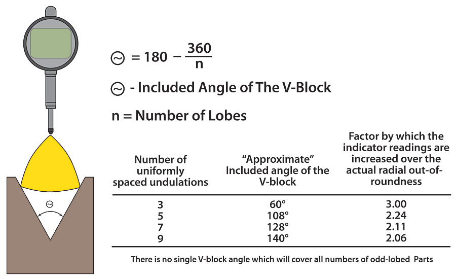
However, even this is not truly accurate as a measure of runout. As you can see from Figures 3A and 3B, V-blocks tend to diminish TIR readings on even-lobed parts—sometimes even to 0!—and increase TIR readings on odd-lobed parts, sometimes by as much as a factor of 3. Clearly, this has some drawbacks when attempting to use it as a substitute for runout, and definitely is not an effective substitute for roundness.
Runout vs. Roundness
By the same token, people confuse runout with roundness. I usually tell people that runout is roundness pluswhatever centering error you have. If I were to put that indicator on the shaft noted in Figure 2, and rotate it about those centers, I would see some error in TIR that would have to do with how round this thing was. But I would also see this long slow sweep, or wobble that happened once per revolution that had to do with the fact that these centers were not concentric with the surface I was measuring.
This wobble is included in the runout as well as roundness. Now, when people first grasp this, they immediately assume that runout must always be larger than roundness. But the fact is that while runout is usuallygreater than roundness, it doesn’t always have to be. Roundness is departure from a true circle, so if I had a dent in the part that happened to be just exactly opposite the direction the centers were off, I could get a runout number that was lessthan the runout. While unlikely, it is certainly possible and can lead to incorrect conclusions.
Conclusion
The bottom line (or circle!) is that to measure most form tolerances you need to take care to measure only the form, without location errors clouding the picture. It is tempting to think that you are being conservative if you measure TIR, but this is not the case. In fact, it might very well be that roundness is actually worse than the TIR. So if shape is important to you—and often it is—make sure you take its proper measure.
Looking for a reprint of this article?
From high-res PDFs to custom plaques, order your copy today!


