The Next Quantum Leap in Form Measurement
Industry is rapidly shifting towards micron level tolerance requirements.

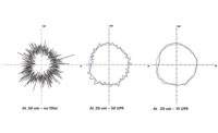
New ISO Geometrical Product Specifications give us the potential to specify form tolerances on parts in new ways that may be beneficial to the function of a component. Source: Mahr

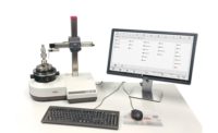
Figure 1. In order to eliminate straightness error from a guideway using the Simple Static Model, the machine is moved slowly along the way while the out-of-straightness is measured with some other system with a higher level of accuracy, such as a laser interferometer, or known artifacts like optical flats, cylinders for cylindricity machines, or master balls for roundness testers. Source: Mahr

Truly practical real time error compensation requires enough computer power to process large amounts of data very quickly. Source: Mahr

Under the new ISO Form Standards, RONt, or roundness total, is determined as the total value of the distance to the highest peak and the distance to the lowest valley from a reference circle. But the mean reference geometry concept also allows you to get those separately: mean to the peak is RONp, and mean to the valley is RONv, analogous to the Rp and Rv in the world of roughness. You can also get the root mean square distance of all profile points from the reference circle as RONq. Source: Mahr

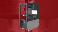
Utilizing real time error compensation, this device is designed to take reference quality 3-D and form measurements onto the shop floor. Source: Mahr


We usually think of a “quantum leap” as a big thing, a great change or advance, and often when we are using this term, it is. Yet the term actually originates from atomic science and describes an electron moving from one energy level to another. This is a very tiny change indeed, however significant it is for the electron involved.
The next quantum leap in form measurement will be of similar proportion: very small in scale but significant in impact. In this “next big thing,” microns will be considered a gross measure and nanometers will become targets of interest. We’re not quite fully there yet, of course, but industry is rapidly shifting towards micron level tolerance requirements and the need for high precision manufacturing and measurement is growing. While most current projects are related to scientific applications in aerospace and nuclear, many micro-mechanical elements of optics and electronics also require higher and higher levels of fit, form and function. In addition, economical low-emission engines, high-performance hydraulics, and medical diagnostic equipment all require increasingly accurate reliable components that meet not only the required dimensions but also the required shape.
Tech TipsIn order to achieve the highest levels of measurement accuracy, all the sources of error must be dealt with appropriately. We typically think of the machine doing the measurement as the key ingredient, and often it is, but we should never forget that the machine is part of a complete measurement process. We need to be concerned about things like the temperature in the environment, air flow around the machine, and sunlight or other radiant heat sources. |
All of this means not only that measurement is becoming more important, but that it must also become more accurate and precise. This is especially true of form measurement, which is perhaps the ultimate measure of 3-D functionality. Even today, the demands of small parts with submicron tolerances, such as the needles used in high pressure diesel injection systems, cannot be met with conventional measuring devices.
Like quantum leap, the terms ‘micron’ and ‘nanometer’ seem to be batted about quite casually these days. But to put things in perspective, remember that a human hair is about 60 microns thick. A nanometer is one thousandth of a micron (1 x 10⁻⁹) which makes it 60,000 times smaller than a typical human hair! The diameter of a helium atom is 0.1 nm. So when we start to talk about nanometers, we’re talking really small things that are close to the molecular level in size. To approach this level of accuracy in form measurement, we’ll need to look at several things.
An All-Inclusive Strategy
In order to achieve the highest levels of measurement accuracy, all the sources of error must be dealt with appropriately. We typically think of the machine doing the measurement as the key ingredient, and often it is, but we should never forget that the machine is part of a complete measurement process, including the environment that it is placed in and the way the operator using the machine interacts with it. We need to be concerned about things like the temperature in the environment, air flow around the machine, and sunlight or other radiant heat sources. We also need to take care about how the component being measured is handled by the operator. The body heat of the person can cause small size changes to occur while loading the part. The operator needs to take care that the clamping force applied by whatever is holding the part does not distort it during measurement.
These factors, which are important in all measurement processes, become especially important as tolerances approach micron and submicron levels. Even temperature, which many people discount as irrelevant to very small parts has a proportional influence and can become a significant contributor to measurement errors at this level. Just as we are now used to the need for “clean room” manufacturing environments for things like medical devices, we’re going to need to get used to “metrology room” manufacturing environments for submicron tolerance parts.
Error Compensation
There are five types of errors in machines that can affect mechanical motion: straightness of guideways, accuracy of the position measuring system, angular misalignment between the guideways and position measuring system, deformation of axes under load, and deformation of axes under dynamic conditions. These are nothing new, of course, and ideas to compensate for them have been around for many, many years. Early clockmakers had mechanisms to make their clocks more accurate, and “corrector bars” or “corrector systems” for both metrology systems and machine tools have been documented as early as 1760. But it is only in the past 30 years or so, with the advent of readily available and affordable computing technology, that what most of us think of as error compensation has come into common practice.
But in the submicron world, it is important to understand exactly what is meant by error compensation. Nearly all machines that are error compensated use the Simple Static Model. Application of this model is fairly straightforward, as illustrated in Figure 1. In order to eliminate straightness error from a guideway, the machine is moved slowly along the way while the out-of-straightness is measured with some other system with a higher level of accuracy, such as a laser interferometer, or known artifacts like optical flats, cylinders for cylindricity machines, or master balls for roundness testers. This measured error information is stored in the machine’s controller and when other measurements are made, the error information is subtracted from the actual measurement to obtain a corrected measurement.
The same simple static approach can be used to compensate for errors of position and errors of angularity. But static error compensation only accounts for static errors. Drop an engine block or some other heavy component onto the machine, or move the machine quickly and all bets are off. However, if you know what the dynamic deformations of load or motion are, it might be possible—at least theoretically—to build a computer model that predicts how the machine will react under certain loads and at certain speeds. Then it should be possible to add in the known static error to generate a total error value in what is known as a Dynamic Error Model.
To date, however, this theory of Dynamic Error Modeling has not proven practical. But while predicting the effects of load and inertia in a dynamic error model may still be problematic, measuring them while they happen is possible. Indeed, the idea of Real Time Error compensation has been around for a long time, but has lacked the computer power to process enough data fast enough to make it practical. The basic idea is to have a measuring machine to measure the part, and another machine to measure the measuring machine. This second measuring machine, called a metrology frame, must be undisturbed by the weight of the parts and the speed of motion of the machine that’s measuring the parts. It must be physically separate from the measuring machine.
While there are metrology frame systems available today, the idea of two machines in one is extremely unique and requires a great deal of computing power to measure all of these motions and calculate the corrected position of the probe in 3D space during a measurement. This happens thousands of times per second in typical measurements and ensures the submicron capability required by the most challenging form measurement applications.
Utilize New ISO Standards
In 2011 ISO introduced new Geometrical Product Specifications for Roundness (12181), Cylindricity (12180), Straightness (12780) and Flatness (12781). Designed more to set the stage for future development than govern immediate needs, these new standards give us the potential to specify form tolerances on parts in new ways that may be beneficial to the function of a component, and may be of significant help in reaching the goal of nanometer form measurement. This is not because they offer more accuracy, but by being functional in nature, they can be more specific.
How they operate is fairly straightforward. In the old days (i.e., pre-April 2011, when these standards were officially released) when we talked about any form characteristic, it was always in terms of a single number, derived from a maximum peak to valley value which deviated from an ideal geometric form. So if we looked at the roundness of something, we would take a roundness trace, collecting data as to how a surface varied around the circumference of something. To determine roundness, we would first determine some type of best-fit circle (the ideal geometric form) and then find the highest peak outside the best-fit circle and the lowest valley inside the best-fit circle. The sum total of those distances from the best-fit circle was the roundness value: it was defined, simply, as the maximum deviation from a perfect circle.
The new standards allow other options than simply the maximum deviation from an ideal geometric form to be specified. We still fit an ideal geometric form of some kind, but now we have the option of looking at parameters that would put tolerances on the peaks separately from the valleys, as well as other refinements to the total variation.
To understand how this works, look at the world of surface metrology, which is where these parameters have some close cousins. In the world of roughness, for many decades we have calculated parameters by fitting a mean line through the measured profile, and then used the relationship between the profile points and the mean line to calculate all sorts of parameters. The most typical calculation we make is the average distance all the profile points are from the mean line, which is Ra. We can also get parameters such as the root mean square distance of the profile points, Rq, or the maximum peak height separated from valley depth, Rp and Rv, and so on. In surface metrology, a surface can be mathematically characterized in any number of different ways to assess its functionality. In fact, there are at present about a hundred parameters for assessing surface features defined in various international, national, and company internal standards.
It is exactly this desire to better characterize and define the allowable form errors on a surface so that these can be matched to the function of the surface that is driving this change in the form standards. Consider a hydraulic cylinder sliding back and forth through a seal. You could probably tolerate valleys on the surface of the cylinder (even though they might cause leakage) a lot more than you could tolerate peaks sticking up and gouging into the seal as the cylinder slides back and forth. So in addition to RONt (Total Roundness), you might want to specify a peak value for RONp (Peak Roundness) that is very tight, and give a little more room using RONv (Valley Roundness) on the valleys.
Being able to focus specifically on those areas of part geometry most affecting part function, will effectively narrow the tolerance range for those parts and move us closer to nanometer form.
Marry Machining and Metrology
The final step in bringing form to the nanometer level will involve taking the real time error compensation and the metrology frame concept back to the machine tools making the parts. For modern machine tools only a few examples of this exist in regular use. Most examples are in national laboratories and academic institutions. One of the earliest documented examples in the modern era is the Large Optics Diamond Turning Machine (LODTM) at the Lawrence Livermore National Laboratory. This machine was developed in the days of the Strategic Defense Initiative (euphemistically known as Star Wars) when they needed to make very large, very, very high precision optics that could focus on targets and direct missiles, and where even very tiny angular errors had to be eliminated. The LODTM is a machine tool that uses a single-point diamond as the tool to remove tiny precise amounts of material from whatever it is that it’s machining.
Lawrence Livermore reported in 1983 that they had a separate metrology frame around this machine which used laser interferometers to measure the positioning of the tool on the diamond turning system, which was able to take into account things like the cutting force of the diamond and the corresponding machine distortion. The LODTM was considered by many to be the highest precision machining device built up to that point in time.
The highest precision machine tools currently available commercially are the single point diamond tools used predominately in the optics industry. These systems use high-resolution linear scales to provide precise axis position feedback and on-machine workpiece measurement and error compensation systems. While this is not quite the full metrology frame capability, it points the way to what can and needs to be done to bring the machining capability to the next level.
Summary
The next quantum leap in form measurement will target submicron and even nanometer tolerances. To achieve this level of accuracy we will have to apply metrology lab conditions to both measuring and manufacturing: real time, metrology frame error compensation systems to both machine tools and measuring machines; and become much more specific in developing function related form measurement parameters under the new ISO geometry standards. Q
Pat Nugent is vice president, metrology systems at Mahr Federal Inc. For more information, email patrick.nugent@mahr.com or visit
Looking for a reprint of this article?
From high-res PDFs to custom plaques, order your copy today!


