Internal Part Thread Inspection

Figure 1


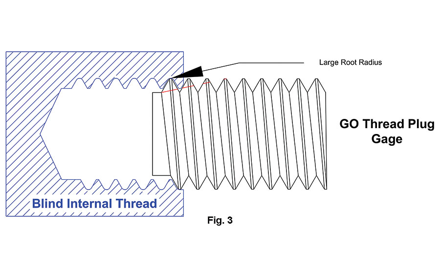
Figure 3.

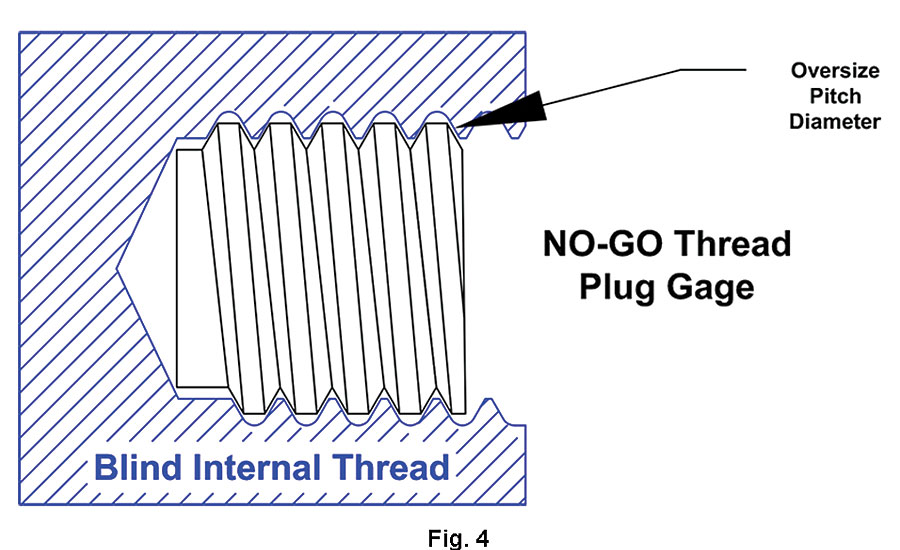
Figure 4.


How do you measure an internal thread on a part? How do you decide what you need? The thread description and thread data are critical to answering these questions. The thread description states the nominal diameter, threads per inch and thread series for UN Threads. If the thread is metric, it will state the nominal diameter and pitch for M Series Metric Threads. A Class of Fit and any special requirements are required for both the Unified (Inch) and M Series (Metric) threads.
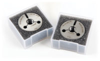
Do you need to report the actual measured values of the thread or do you need a pass/fail inspection? If actual measured values of the thread are required, or you are manufacturing threaded parts to System 22 or 23 (ASME B1.3), or possibly making threads per SAE AS8879 Category 2, you will need variable gages as well as Fixed Limit Go / No-Go (pass/fail) gages to inspect the thread. The starting point, or ending point if pass/fail meets your requirements, is the use of a Go / No-Go inspection method. One of the basic pass/fail inspection methods is to use Fixed Limit Go / No-Go gages. Go / No-Go gages include working thread plug gages for inspecting internal part threads and thread ring gages for inspecting external part threads.
TECH TIPS
|
Working thread plug and thread ring gages, in the United States, are manufactured and inspected per ASME B1.2 for Unified Inch Screw Threads and ASME B1.16M for M Series Metric Screw Threads. Gages per these standards, including cylindrical gages for measuring major diameter on external threads and minor diameter on internal threads, meet the requirements of System 21 per ASME B1.3. These standards dictate the use, functions, sizes, and tolerances for the gages. These gages are used in conjunction with the ASME B1.1, Unified Inch Screw Threads and ASME B1.13M, Metric Screw Threads: M Profile part standards. In this article, we will be focusing on the function and use of working thread plug gages to inspect internal part threads.
One of the most important rules in part thread inspection is to insure that the part threads are clean, free of burrs and other obstructions. Incomplete threads or threads with poor form or surface finish will also cause problems and adversely affect the function of the gage and the inspection of the threaded part. The most important tip to remember is: never force a gage into the part. If the gage stops, remove it from the part, clean and check the part for damage. Check the gage for damage or foreign material in the root as well. Thread gages are not die clean out, cutting or deburring tools. Forcing a gage into the part not only damages the part, it can also shorten the life or damage the gage.
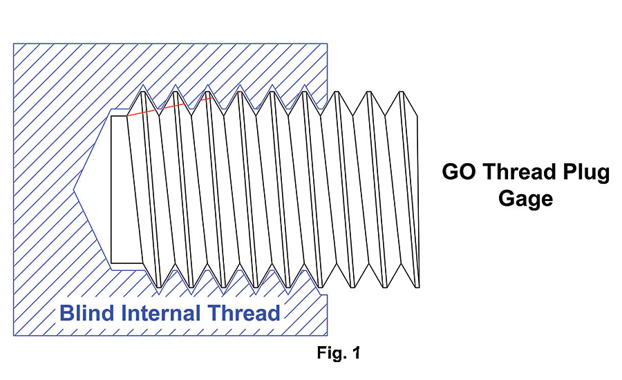
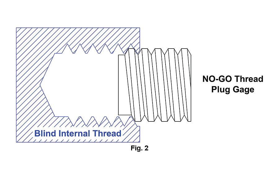
Go / No-Go gaging is direct and generally simple. If the Go fits (Fig. 1) and the No-Go does not (Fig. 2), the functional thread is in tolerance. The potential for problems occurs when the product begins to drift towards the extremes of the tolerance. This is when a better understanding of the gage design, tolerances and functions becomes critical.
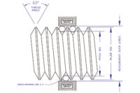
Per ASME B1.2-1983, the “Go thread plug gage must enter and pass through the full-threaded length of the product freely. The Go thread plug gage is a cumulative check of all thread elements except minor diameter.” The pitch diameter of the Go thread plug gage is the same as the minimum pitch diameter of the internal part thread with a plus tolerance. The Go thread plug gage major diameter is equal to the minimum major diameter of the internal part thread with a plus tolerance. The major diameter of the Go thread plug gage also represents or exceeds the max major diameter of the external mating thread. The minor diameter of the Go thread plug gage is a clearance feature. The only requirement is that the minor diameter of the Go thread plug gage is cleared beyond theoretical sharp. The purpose of the Go is to insure assembly with the mating external part. It does not measure the major or minor diameter of the internal thread. Simply put, the Go thread plug gage insures assembly with an in-tolerance external thread.
The No-Go thread plug gage only inspects the maximum functional pitch diameter of the internal part thread. The major and minor diameters of the No-Go thread plug gage are clearance dimensions. It is important to note that the major diameter of the No-Go thread plug gage is always smaller than the major diameter of the Go thread plug gage for 60° screw threads. This is done by design to insure that, if the No-Go gage fits into the internal part thread, it means that the internal part thread pitch diameter is oversize. A properly manufactured No-Go thread plug gage should never contact either the major or the minor diameter of the internal part thread.
No-Go acceptance rules generate most of the questions we receive on thread gages. Both the ASME B1.2 and the ASME B1.16M have rules and stated exceptions for the number of turns a No-Go thread plug gage may enter the internal part thread. The ASME B1.2-1983 for UN Series Inch Screw Threads states the No-Go may enter up to three turns. The gages must not be forced. Other considerations that may necessitate a change to this practice are exceptionally thin or ductile material, small number of threads, etc. The M Series Metric Screw Threads per ASME B1.16M are different. The Metric threads only allow the No-Go thread plug gage to enter up to two turns with the same exceptions as the Unified Inch Screw Threads. The purpose of this allowance is to take into account the incomplete thread on the part and additional wear on the starting threads on the No-Go Thread plug gage.
What does it mean when the Go does not enter the internal part thread? This would indicate that the functional thread is undersize or too small. Many times this means that the internal part thread is undersize at the pitch diameter or at the major diameter. It may also indicate a problem with the thread form or the lead of the thread. When this happens, a review of the thread cutting or forming tool geometry should occur. The manner in which the internal part thread is manufactured or the materials used may have an impact on the possible causes.
When the No-Go enters the internal part thread, the pitch diameter is oversize. Confusion occurs when the operator makes the thread and the Go does not enter (Fig. 3) and the No-Go does (Fig. 4). In many machining operations, when the Go does not enter, the operators makes small incremental changes in the cutting tools or depth of cut until the Go thread plug gage passes freely through the entire length of the internal thread. Once they hit the point where the Go enters, they then apply the No-Go. In theory, the No-Go should not enter. This indicates that they have a good internal part thread. When both the Go and No-Go do pass through the internal thread or the Go does not and the No-Go does enter, the understanding of the gage function will help solve the problem. Because the only feature on the Go thread plug gage that is larger than the No-Go thread plug is the major diameter, it is the first place to look. This problem usually indicates a worn cutting tool that has a major diameter that is undersize or is creating a radius in the root of the internal thread that is too large and interferes with the major diameter of the Go thread plug major diameter. Remember, not only does the major diameter of the Go thread plug represent the min major of the internal part, it also represents the max major diameter of the external mating part. The key is understanding what the design purpose of the gage is and how variations in the manufacture of the internal part thread affect the gaging results. Major diameter interference covers the largest percentage of these problems. It is not the only possible cause. Poor lead, or out of round threads can cause some of these issues as well.
Do not forget to measure the major diameter of external part threads and the minor diameter of internal part threads. The previously mentioned ASME standards list the sizes for cylindrical Class Z ring gages to inspect the external part thread major and cylindrical Class Z minor diameter check plug gages for internal part threads. Measuring these features on the part threads is critical to insuring assembly of the mating parts. Other major or minor diameter inspection tools with equal or better accuracy may be used as well.
Be sure to share all of the part thread data or drawings when purchasing or quoting gages.
Looking for a reprint of this article?
From high-res PDFs to custom plaques, order your copy today!


