Machine Vision Applications: The Process of Developing a Complete Solution
The first step is to establish the requirements and determine if it is possible.

A calibration grid seated on a piece of tooling above a red backlight.

The five phases associated with machine vision applications with potential sub-categories.

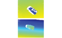
A prototype vision station that captures images of a part.


The term machine vision can imply a computer having a set of eyes for an inspection. To develop a complete solution for machine vision applications, vision engineers execute a series of tasks that usually fall into five categories: plan, design, build, integrate, and validate.
Plan
For many vision engineers, the first step to any solution is to establish the requirements for each inspection and to determine if it is possible. Several factors need to be considered, such as:
- What is being inspected
- Number of inspections required
- Speed of inspections
- Restrictions from mechanical design
- Performance requirements
- Time and costs
The planning phase flows into the design phase for verification purposes. To ensure the requirements are attainable, prototyping is done. If the vision engineer believes the inspection is achievable, prototyping may not be required. However, verification is always beneficial as changes made later into the solution will affect time and costs.
Design
Based on the inspection requirements, an initial vision design is created and tested for each vision application. There can be several vision stations, all with different optical setups. When designing a vision station, there are several factors that need to be considered for each camera, lens, and light.
- Camera Specifications
- Number of Cameras
- Type of Camera
- Monochrome or Color
- Resolution
- Frame rates
- Communication Protocol
- Exposure/Shutter Speed
- Gain
- Lens Specifications
- Type of lens
- Focal Length
- Working distance
- Spacer
- Field of view
- Filter
- Aperture
- Light Specifications
- Number of lights
- Type of light
- Size
- Color
- Distance from part
- Intensity
Once some factors are determined, a vision design prototype is set up to capture images of a sample part. Key features must be detected by the software by having the right amount of contrast in the image. This process involves adjusting the optical equipment.
An image consists of an array of pixels which is usually defined by a resolution. Machine vision software uses these pixels, as well as predetermined algorithms to define certain features of a part from the image. It follows the same concept as facial recognition software. This software searches the image for certain pixel arrangements to identify features of a face. For example, eyes will have darker pixels around the edges as well as dark pixels in the center of eyes. The software uses the algorithms to analyze features, and recognize a face. Similarly, machine vision software follows the same concept. These algorithms are developed by vision engineers using machine vision software.
There may be certain mechanical restrictions as well that would require additional optical equipment such as mirrors. There can also be mechanical restrictions that require change in design. For example, the working distance may need to be between 300mm and 320mm because of some tooling within the automation that surrounds the optics. There is a chance the lens would need to be changed, along with addition of extension tubes.
If the image does not meet the requirements, troubleshoot. Change various parameters to allow for a more suitable image. The lighting may need to be changed or a polarizer may need to be added. Prototyping allows vision engineers to verify vision designs as well as create them.
A regular machine vision camera usually requires a vision controller. If a smart camera is being used, an external vision controller is not required. A vision controller is a dedicated unit for performing communications with the optical equipment, such as cameras and lights. The vision controller should have the capabilities of meeting inspection requirements. This means it must be able to handle communicating with the equipment being used for the inspection as well as other I/O protocols required.
During this stage, it should be clear whether the requirement of the vision inspection is attainable or not. The software should be able to detect the required features needed to process the inspection. To verify the software is able to detect edges, use a few tools that will be used during the inspection (i.e. edge locate tools) to ensure the software can detect certain edges. Attempting to alter the design past this point may increase costs of the solution. Ensure confidence with the vision design at this stage.
Develop
Machine vision software can have various tools that help analyze features in parts. The first thing to do before building the code is to use a sample image to plan out how the code will be built. This will also depend on which machine vision software is going to be used. Using the setup already designed, grab several images of good and bad parts to use during this phase.
Different software can have different toolsets. Certain software may not have the capability to keep up with cycle time of the automation. If an inspection requires a quick cycle time, the full inspection must be completed within that time. It all comes back to the requirements for the inspection to decide which software to use.
Depending on the requirements of the inspection, there are several factors to consider when building the code. Some examples include:
- Do multiple images need to be captured by each camera of each part?
- What are the features that need to be inspected?
- How frequent will the light need to strobe?
- What are you trying to analyze of the part?
- What tools will need to be used for the inspection? (Edge tool, “blob” tool, calibration, etc.)
- How will calibration be done?
- Is there something the software is communicating with?
- How does ambient lighting play a factor?
- If there is a light involved with the inspection, when will this light trigger? Does it remain on throughout the entire inspection? Does it strobe? If the light needs to be triggered with the camera, this needs to be accounted for with the software as well. If there is a strobe unit involved, how frequently will this unit strobe?
A sequence of tools needs to be executed in the software for an inspection to occur. Tools also need to be placed accordingly to make sure the software only inspects features that need to be inspected. With these tools there needs to be certain logic. For example, if a defect is detected by the software, the part is a fail, output an error code, and display the results.
This information needs to be sent to any external controllers that are being used with the automation. It will allow the machine to know what to do with the part if a part is a pass or fail. With these communications, there also needs to be I/O capabilities to communicate with the rest of the automation.
With the communication, there also needs to be a user interface (UI) that will be easy to understand for the operator. This means making sure that all results are easily visible and any other functions can be used with ease by the operator. Error codes should be easy to understand for the operator as well.
For precise measurements, there needs to be a calibration step that allows the software to be able to measure features from the image. One method for this is using a calibration grid. An image of a calibration grid will be taken from the vision station to allow calibration of the inspection. Most machine vision software will have a tool for this. The tool will have the option to use a calibration grid and it will ask the parameters of that grid.
Integrate
The integration phase is where all the optical equipment is integrated with the rest of the automation. This is where everything comes together as one whole unit.
First thing to do in the integration phase is to make sure all the hardware is configured and mounted onto the automation assembly. Adjust each vision station as per design specifications made in the design phase. Ensure that all communications are functional between all devices.
Using the calibration step developed earlier, calibrate the optical equipment. If a calibration step is done, run that step with the calibration target in the field of view of the camera and capture that image. The software will calibrate its measurements to the calibration target. Ensure that the measurements in the software are the same as actual measurements of the part. If there are lights used for the inspection, adjust the light intensity to meet the required light levels.
Test the optical equipment by triggering several images. If there is a consistent read of good images, test the optical equipment with full automation. Test with good and bad parts to ensure part rejection. Make sure all timing is in sync with regards to automation and optical equipment, to ensure for an effective inspection.
If an inspection does not meet requirements at this stage, troubleshoot. Depending on the issue, there may be something in the code that needs to be changed. Changing code is a simple fix at this point. If there needs to be equipment changes or any other major changes, it may increase time and cost of the solution.
Validate
In this phase, several tests are run to ensure the vision stations meet the requirements outlined at the beginning of the project. The tests are created based off of the requirements for the inspection. One test that should be done for every vision inspection is a repeatability test. A good example of this test is a gage repeatability and reproducibility (GR&R) test. This test checks for variation in the measurements and variation in parts.
If requirements are not met, troubleshoot again. Attempt to fix the inspection by making minor changes, such as changes on the code. This will take less time and resources. At this stage of the project, major changes will take up more time and resources. Once all the testing has passed and all requirements are met, the solution is done.
Companies looking for complete machine vision solutions require quality inspections that are reliable. For vision engineers, these five phases help build complete machine vision solutions with quality and reliability.
Looking for a reprint of this article?
From high-res PDFs to custom plaques, order your copy today!


