Inspection Technology Review for Automotive Bead Dispensing Process
The industry is trending toward 3D for inline bead inspection.

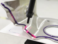
3D inline bead inspection technology.
Bead dispensing is becoming a more and more common process for automotive manufacturing. In automotive body frame and chassis, aluminum is gaining popularity, as manufacturers seek to improve fuel efficiency without sacrificing vehicle integrity or performance. Thin gage aluminum part per se is difficult to weld, not to mention joining two dissimilar materials between aluminum and steel. That is why structural adhesive is becoming an industry trend. The right amount of structural adhesive applied at the right location is crucial to the rigidity of the vehicle body frame.
In powertrain and vehicle final assembly, significant amount of Form-In-Place-Gasket (FIPG) is applied to ensure the sealing performance desired. Neither “too much” nor “too few” is acceptable. The state-of-the-art bead dispensing systems are typically equipped with flow meters or shot meters to measure the total volume of the material dispensed. However, this method cannot tell how much is applied specifically at where. And given the dynamics (viscosity variation, temperature variation, bubbles introduced by barrel change, etc.) of the dispensing process, a more direct in-line inspection technology is truly needed for bead dispensing.
With the tight cycle time and the gel-like nature of the bead, inline noncontact optical inspection is the most suitable solution for good quality control of the dispensing process. Generally, there are two main categories of inline optical bead inspection solutions: 2D and 3D. Two-dimensional solutions are based on contrast (in other words, color or intensity difference) in images acquired to locate and measure the bead. There are several limiting factors to this solution.
First, 2D solutions can only provide 2D information, which is the bead width. It cannot provide cross-section profile, which is what really matters to functionality—wet-out for structural adhesive bonding and sealing for FIPG. Second, performance of 2D solutions is heavily impacted by part color or ambient lighting. High false reject rate is common for 2D solutions in real production environments. It can also miss bad parts when the nozzle scuffs the part surface and leaves a thin film of bead marks without sufficient material to fool the 2D system. This happens often when the part vibrates or the robot program is not fully optimized.

The 3D inline bead inspection technology enables a possible industry paradigm change.
With the limitations mentioned above, 3D is the trend the industry is leaning toward for inline bead inspection. There is a big variety of 3D sensing technologies such as laser triangulation, stereovision, structured lighting, time-of-flight, laser interferometry, etc. Given the inline high-speed continuous imaging requirement, laser triangulation is the technology suitable for bead dispensing application. However, the general-purpose single laser line sensor is not sufficient because of the arbitrary dispensing direction and limited space around the dispensing nozzle. One option is to implement a motorized single laser line to trail the arbitrary dispensing direction. However, the modern dispensing process can reach 400mm/s to 1,000mm/s for high productivity. With this high speed, it is very difficult to have the motor respond quickly and reliably enough to any sharp dispensing direction change. The other option is the 3D inline bead inspection system with multiple laser lines stationary around the nozzle. This sensor design ensures inspection of the bead with no blind corner for any arbitrary dispensing direction.
The 3D inline bead inspection technology enables a possible industry paradigm change. With this instantaneous 3D visualization and inspection capability on the bead, product development is empowered to specify the bead in a manner which is directly related to its functionality; and manufacturing engineering is empowered to better control and optimize the expensive dispensing processes.
Once specific situation is that due to the imperfection of the part fixturing mechanism, the dispensing nozzle turns out to be plowing through the bead as it is being dispensed and ends up with a deep trough. This could cause insufficient wet-out for serious body frame rigidity (safety) concern. But for this case, the commonly-used width tolerance would not fail the part, neither would height tolerance even. However, with the power of full 3D data, the instantaneous volume tolerance can kick in as another level of assurance to fail this part as it is supposed to, which potentially saves customers millions to tens of millions of dollars of a major quality leakage.

One specific situation is that due to the imperfection of the part fixturing mechanism, the dispensing nozzle turns out to be plowing through the bead as it is being dispensed and ends up with a deep trough.
Other aspects to review an inline 3D inspection technology for production bead dispensing process include minimum space required for mounting and plant floor implementation, compatibility with different robots and dispensing equipment, minimum added complexity to robot programming, tolerability of robot speed change, support for high dispensing speed, robustness, traceability, and ease of setup and use. The 3D inline bead inspection technology has proven field success on these aspects. Q
Looking for a reprint of this article?
From high-res PDFs to custom plaques, order your copy today!


