Lighting Basics for Machine Vision
With these steps you are well on your way to finding the right light to highlight the features needed for a great image.

Darkfield versus bright field: The “field” is the background or flat parts of the object. “Bright field” lighting refers to when the field is bright. In this case, the light comes from above the field and is reflected to the camera. “Dark field” is when the flat area is dark. This happens because the light is placed to the side of the field, which reflects the light away from the camera.
Much of the latest news surrounding machine vision is about machine learning and the innovations regarding algorithms. But those algorithms need data to perform correctly. The data in this case is the images. It is imperative to capture the best image possible so that the algorithms can perform at their highest level.
Sifting Noise to Find the Signal
Solid imaging begins by determining what is signal (the useful information) versus noise (the irrelevant, confusing information) in the image and using techniques to highlight the former by creating contrast.
Creating contrast requires understanding the flow of information for machine vision. First, the light source is scattered across an object, and the imager gathers that light to form a digital image. Only then can software begin extracting features (lines, edges, text) within the image to provide useful information (dimensions, part ID) and make a decision (pass, fail, sort). By manipulating the lighting, imagers can create contrast between the useful and irrelevant information.
Employing a simple scientific method makes it easy to figure out the best way to create the necessary contrast:
- What is the part made of, and what will it do to light?
- How will light get to the camera? What is the part geometry and path of the light?
- What lighting type and lighting geometry will give the best contrast for the important features?
- What is the timing of the measurement, and object motion?
By way of example, select a light source in the room, the object to be photographed, and use your eyes as a camera. Now keep two of those items in the same place and only move the third. For example, look at an object and keep your head still while paying attention to where an overhead light is positioned. Now move the object slightly. By doing this you can see certain features on the object highlight or disappear. The steps below expand on this concept.
Let the Part Guide Lighting Choice
The first step involves looking at the part to determine how light interacts with the surface. Is it specular, matte, absorptive, refractive, or a little of everything? Reflective parts such as polished metal will reflect the light at the same angle as the light coming at the object. Matte parts will take light and scatter it all different directions. Some parts have material that will absorb light, such as ink on paper. Glass or liquid objects can change the direction of the light (refraction). Most objects have more than one of these properties. Technicians can take advantage of these differences by setting the light to highlight specific features of interest as part of an automated inspection or sortation system. In short, they can choose to highlight the signal and minimize the noise in any given image.
The second step involves looking at part geometry and imagining the path of the light from the source to the part and from the part to the camera. If there is no path to the camera, that part of the image will be dark. If light reflects to the camera, that part of the image will be bright. Changing the path of the light will brighten or darken different features. A couple of terms that are used frequently for lighting geometry are bright field and dark field. The “field” is the background or flat parts of the object. “Bright field” lighting refers to when the field is bright. In this case, the light comes from above the field and is reflected to the camera. “Dark field” is when the flat area is dark. This happens because the light is placed to the side of the field, which reflects the light away from the camera.

Polarized filters help to reduce glare from highly reflective surfaces such as printed circuit boards. In the first image, multicolored lights are used to illuminate the PCB to show the various hot spots created by direct, unpolarized illumination. The second photo shows the same board with cross polarized light, reducing glare and revealing hidden codes, characters and features.
Select the Best Lighting Method
Armed with the knowledge of what will happen to the light and the path of the light, technicians can decide on the type of light. There are six general ways to provide light to a part.
General bright field illumination. Imagine a ring of light surrounding the camera, looking straight onto the object. Features that are flat and reflective will appear brighter than those that are curved or absorptive. This is great for looking at print on objects.
Coaxial illumination. The camera looks straight at the object, and light comes in straight in-line with the camera. All the light that is in-line and hitting a flat surface will shine directly back up at the camera. Anything flat will be bright. Anything not flat will be dark because if the light hits an angled surface it reflects away from the camera. This method works really well for highlighting scratches or other surface defects.
Dome, or diffuse, illumination (also called cloudy-day illuminator). Think of dome lighting as a big bowl with a hole in the middle. The bowl sits upside down, so the camera is looking through the hole, and the light shines up into the bowl and scatters in every direction. Dome lighting is also called “cloudy-day illuminator.” Imagine being outside on a very cloudy but sunny day. Everything is bright and lit up, but there are no shadows because the clouds diffuse and disperse the light all over the place. This method works great for objects that have a lot of different angles, such as packaging (blister packs and poly bags).
General dark field illumination. The camera looks straight at the object, but the lighting comes in from the very lowest angles. Think of the part as the horizon and the lights as coming in right above the horizon. The light skims across the object and away from the camera. Any bump or dent is highlighted because the light hits it and bounces toward the camera. This method is very effective for highlighting objects with direct part markings.
Backlight illumination. This method uses a flat diffuse light that comes from behind the part and is aimed directly at the camera. The object will block the light so it will appear dark and the background white. This allows the image to have very clear edges. This method is great for measurements and checking the fill level of liquids.
Structured light. With structured lighting, a straight bright line or series of lines are projected onto the object. The bright lines will change depending on the object’s shape. Structured light is useful when the object has black-on-black parts. Black absorbs all the light and it is not visible to the camera. By using a concentrated beam of light, the camera sees the line of light and so can detect a black O-ring on a black plastic part, for instance. If the O-ring is there, the line will be in a certain position in the image, and if the O-ring is missing, the bright line will be in a different position.
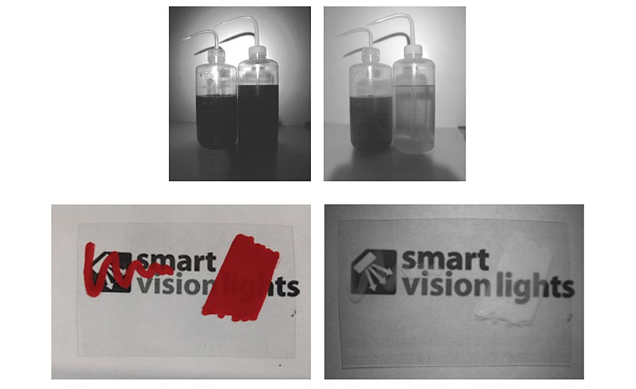
These four short wave infrared (SWIR) pictures show how machine vision designers can use this spectral band to see through paint and differentiate between materials. The two bottles show in images 1 and 2 show alcohol and water, with clear alcohol clearly differentiated in the second image. In the second pair of images, SWIR radiation is able to penetrate the paint on the plastic card, revealing the patterns underneath. This technique is widely used in ports for detecting altered storage containers.
Not All Light Is Good
When deploying any of the methods above there are a couple items to note because they can introduce noise. First, be aware of the ambient light. As much as lighting will help your image, unwanted light can hurt the image. Polarizers can reduce glare from non-metal parts. You should select a light that will be brighter than the factory lights. Be aware of any sunlight and if needed shroud the area to keep unwanted light away. Second, be aware that if you double the distance of the path of light the light is four times dimmer. The brightness of the lights is important because of the exposure time needed to capture an image. The exposure time is the time the camera collects light from the object. The longer the exposure time the fewer images a camera can collect in a given time. If the object is moving, the longer exposure will cause blur in the image. So having a dim light will likely have blurry features and reduce throughput. It is important to note in the instances where you need lights further away, consider using focused lights or lights that strobe (overdrive).
Lastly, we need to discuss color. Using colored lights or color filters with a monochromatic camera are a highly effective way of highlighting or hiding features in an image. Green objects are green because they reflect green wavelengths and absorb blue and red wavelengths. If you have not done so recently, please review a color wheel. It is helpful to know what colors are opposite each other on the wheel. You can use like colors to brighten an object and opposite colors to darken an object. For example, if you shine blue light at blue objects, they will appear white in the monochromatic image because they are reflecting all the blue light. The other colors absorb the blue light and will be darker. At the same time, CMOS imagers are more sensitive to red light, which also avoids potential UV eye damage issues from blue and shorter wavelengths. Color filters are used to exclude the noise. When filters are put in front of the camera they can cut out light wavelengths that are not needed or they can only allow the wavelength that is needed.
Even though there are infinite possibilities of objects to inspect, with these steps you are well on your way to finding the right light to highlight the features needed for a great image. V&S
Looking for a reprint of this article?
From high-res PDFs to custom plaques, order your copy today!


