Quality 101: Laser Tracking Fundamentals

The
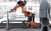
use of six degrees of freedom systems continues to expand in the automotive and
aerospace industries. Source: Leica Geosystems

The
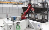
use of six degrees of freedom systems continues to expand in the automotive and
aerospace industries. Source: Leica Geosystems
A laser tracker is essentially a portable coordinate measurement system that uses a laser beam to accurately measure and inspect in a spherical volume of up to 260 feet. A laser tracker can gather information in three different ways: by following a small- mirrored sphere; by tracking a wireless, armless contact probe; or by tracking a handheld scanner. The operator will choose the most appropriate data acquisition method, or combination of tracking tools, for the job at hand. And the possible applications for laser tracker-based systems have grown to include prototyping and reverse engineering, tooling inspection and part mating.
The basic setup includes the tracker itself tracking a mirrored sphere, a computer running the application software and a controller unit for the laser tracker. Jig component inspection or wing component assembly are some of the typical mirrored sphere applications in the aerospace industry. Similar tooling applications also are common in the automotive industry. A metrology technician places the sphere in the position to be inspected, and the laser tracker determines its exact coordinates in 3-D space. Here the major advantage of a laser tracker is that it can be easily transported to a part on the shop floor, such as an aircraft wing more than 100 feet long. The sheer size and length of the wing renders it unsuitable for traditional coordinate measuring machine (CMM) inspection.

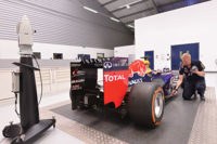
Laser
trackers are now a standard-issue metrology tool for in-place inspection of
large parts and assemblies in both the automotive and aerospace industries.
Source: Leica Geosystems
The probing and scanning devices are coupled to a laser tracker by means of a digital camera system operating with visible light and infrared (IR) radiation, an optical vario zoom and a motor for vertical, angular movement. Mounted onto a laser tracker, the camera system continuously follows the target device and captures the images of the IR LEDs located on the target device. The camera’s incremental angle encoder is used to provide the vertical angular movement of the camera itself, based on tracker guidance angles.
A reflector, not unlike those embedded in the mirrored sphere, is integrated into the target device. Multiple LEDs located on the target device’s surface, together with the reflector, represent the measurement targets of the complete system. Six measurement parameters describe the position of the target device in relation to the laser tracker. These are the three position parameters-X, Y and Z-and three orientation parameters-pitch, yaw and roll. Together, they comprise the six degrees of freedom (6DOF).
The use of 6DOF systems continues to expand in the automotive and aerospace industries. Laser trackers allow manufacturers to cut inspection times by taking the CMM directly to the part, rather than transporting the part to the metrology lab. Tooling can be probed or scanned in-line, which minimizes interruptions to the manufacturing process, lowers inspection costs and reduces secondary costs that result from halting the production to facilitate inspection. These multiple savings possibilities open the portable CMM door to mid-size enterprises that have been waiting for a versatile metrology solution with a faster return on investment.
Looking for a reprint of this article?
From high-res PDFs to custom plaques, order your copy today!


