Vision & Sensors - Imaging
3-D Imaging Enters the Machine Vision World
Consider these 3-D imaging techniques for machine vision.

(left) Kinect projected IR laser pattern. (right) Live 3-D image acquired by the Kinect. Source: MoviMED

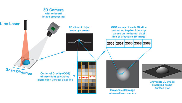
Laser triangulation with single camera and laser using the Center of Gravity method. Source: MoviMED

(left) TOF image returned from camera. (right) TOF image displayed as 3-D surface plot. Source: MoviMED


Machine vision as a subset of computer science has been around for more than 20 years. However, only in recent years has 3-D imaging entered the machine vision world in a more noticeable way. Countless approaches to 3-D vision have been researched, but only a few of these techniques have been commercialized. Probably one of the most prominent and successful 3-D imaging products has been the Microsoft Kinect for the Xbox 360 game console. The Kinect uses a “structured light” principle to calculate depth. It has an additional color camera built in to allow for skin color to be applied to the 3-D scene. There are several other common 3-D imaging techniques such as stereo vision, time of flight (TOF), laser triangulation and interferometry to name a few. Others are intentionally omitted as this article is not intended to discuss them all.
Interferometry
Most machine vision applications have an ever increasing demand for scan speed and spatial resolution. Three-dimensional applications are no exception. As machine vision engineers know all too well, the need to capture larger fields of view (FOV) often competes with the desired (or available) resolution and scan speed of the system. One application of 3-D imaging that tends to be FOV and speed agnostic is metrology. Here it is more desirable to achieve the highest possible spatial resolution in the X, Y and Z dimension. A typical 3-D imaging technique used for 3-D metrology systems is based on vertical scanning white light interferometry.
This technique makes use of interference patterns and extracts height based on fringe contrast. Compared to most other 3-D imaging techniques, this one achieves resolutions beyond the refraction limit of visible light. These systems are capable to resolve down to single digit nanometers (nm). The approximate field of view (FOV) for such a system is usually limited to about 200 microns (µm) x 200 µm x 10 µm. Vertical motion of a lens element or the scanning head is needed, thus adding to the scan time. These limitations make using this particular technique outside of metrology undesirable, especially for machine vision applications involving moving parts.
Structured Light
As mentioned earlier, the Microsoft Kinect is probably the best known 3-D imaging system based on structured light. Although it made its debut in the consumer electronics and video game market, the use of this technology is already spilling over into the industrial machine vision arena. There are attempts to use the Kinect for pick-and-place robotic applications, machine vision software vendors are releasing Kinect drivers and interfaces, and universities are starting machine vision research based on the Kinect. It is a very capable, low cost 3-D and 2-D imaging platform with 1280 x 1024 pixels at a sample rate of 15 frames per second (fps).
The Kinect has a built-in infrared (IR) laser pattern projector that is invisible to the human eye. It projects an IR dot pattern into its field of view. It uses an astigmatic lens (different focal length for X and Y axis) to differentiate between near and far objects based on the elongation and direction of the projected dots. It also combines two 3-D imaging techniques: depth from focus and depth from stereo. The limitations of this system when it comes to applied machine vision are the fixed projection and imaging optics, and the overall form factor, which was designed for the living room. Nonetheless, the Kinect is one of the most powerful new 3-D imaging systems available despite its low cost.
Binocular Stereo Vision
This technique seems to be making a comeback in recent years. Whether in medical imaging for minimal invasive surgery or for autonomous robotics applications, using two cameras at a defined angle to create depth perception is a relatively intuitive approach to 3-D imaging because it closely resembles human vision. However, the geometric algorithms used to process the images can quickly become more complex if movement of either camera or the scenery is introduced. Depending on the accuracy requirements, both cameras need to be synchronized to avoid a temporal error in image capture, which would lead to an error in depth and positional perception.
Both cameras also need to have the same lens and exact focal distance setup to avoid differences in magnifications. Implementing a stereo vision system with zoom lenses, for example, adds another layer of complexity because the focal lengths of the lenses can change, requiring the relative angles of the cameras to change. The more controlled the environment, the easier it will be to calibrate a stereo vision system. A typical result image is referred to as a disparity map or difference map from which the user may extract further information of the object(s) under observation.
Time of Flight
There are only a few time of flight cameras commercially available for machine vision applications. Some of them are disguised as smart 3-D sensors. These sensors or cameras usually use an array of infrared LEDs, with a wavelength around 780 to 900 nm. The generation of the IR light is tightly synchronized with the detector in the sensor to determine a phase shift and therefore allow the calculation of time of flight. From the time of flight, the sensor is able to calculate distance to the object from which the light bounced back. One of the biggest shortcomings with the currently available TOF sensors and cameras is spatial resolution mainly in X and Y. Sensor resolutions are typically in the range of 175 x 145 pixels. Usually, the lens is not interchangeable, limiting this technology to a fixed envelope. There are a few startup companies on the market that are trying to address the demand for higher pixel resolution.
Laser Triangulation
By far the most commonly found 3-D technique in today’s machine vision applications is based on laser triangulation. Typically a visible light laser diode is used with either a point or line projection optic in combination with a 2-D complementary metal oxide semiconductor (CMOS) or charge-coupled device (CCD) camera. Sometimes all of these elements are incorporated into a sealed sensor enclosure. There are several different categories of these laser triangulation sensors. The simplest form is a 1-D distance sensor. A laser point is projected onto a surface and bounced back to either a positional sensitive sensor or CMOS/CCD array. Triangulation is used to calculate the effective distance from sensor to surface. It is possible to measure a single point distance, or with the addition of a motion system, perform a point-by-point scan of a profile or entire surface.
The next category comprises the 2 ½ D sensors, which are essentially the same as the 1-D sensor, but with a laser line rather than a single point. With a 2 ½ D sensor it is possible to capture a cross-sectional profile of the object in a single scan instance. A true 3-D laser triangulation system has the ability to buffer several of these 2 ½ D profiles in memory and transfer a complete 3-D image or perform processing on the complete image in memory based on algorithms available in its firmware. The typical image format from these 3-D cameras or systems is a 16-bit “height map.” All X and Y positions are identical to what one would expect from a 2-D image. The Z height information is contained in the form of intensity (brightness) values. For calibrated sensor outputs, the image format can also be a floating point type with height values in millimeter (mm) for example.
The laser triangulation technique is commonly found in machine vision because it combines good resolution with speed, and usually offers flexibility with respect to working distance and field of view. However, as with any other 3-D method, this one also has its limitations and challenges.
Let’s first take a look at how height is being calculated from a single laser profile projected over an object. Assuming the laser line is in the predefined field of view or area of interest (AOI) of the camera, the center of the laser line needs to be determined. This is due to the way the laser light is being reflected off the surface and laser speckling. In other words, the laser line appears wider than it actually is.
There are three common algorithms for finding the center of the laser line. All algorithms search for the center of the line based on one pixel column at a time. The Y location of the determined center in any given pixel column together with the triangulation angle is converted into Z height values. The peak algorithm looks for the brightest pixel in the column. The threshold algorithm looks for a set threshold pixel value. Both of these algorithms are fast but limited to full pixel resolution only. The third algorithm is based on calculating the center of gravity (COG) of the usually Gaussian distribution of the laser line thickness. The COG method allows for using sub-pixel estimation thus making height measurements more accurate. One drawback of this method is that it is very processor intensive and it may slow down the scanning speed of the 3-D camera significantly unless the camera has a dedicated processor to cope with it.
Now that we know how the 3-D images are being constructed, let’s look at typical challenges encountered in applied 3-D imaging using this technique.
Surface reflectance is one of the biggest challenges. Reflectance is the surface’s ability to reflect any given wavelength of light. A laser is a monochromatic light source, for instance 660 nm (red). Scanning a dull, black rubber material such as a tire may cause most of the red laser line to be absorbed into its surface such that very little light will be reflected into the camera. Some ways to mitigate this low signal strength are to open the aperture of the lens, decrease the scanning speed, or increase the laser power. The opposite will be true for a shiny surface to some degree. Acquiring a clean image becomes more challenging when a surface consists of both dull and shiny parts, causing either over or under exposure.
Some more sophisticated 3-D cameras have an extended dynamic range and multi-slope scanning ability to help address these challenges. Besides surface finish, there are also geometric challenges that often occur. These are caused primarily by the triangulation angle. Something as simple as a 90 degree vertical wall can cause inaccurate results, depending on part orientation and triangulation setup. Sometimes the only way to solve a geometric challenge is to employ a second laser, a second camera or both, in which case both cameras and or both lasers need to be accurately aligned and calibrated to each other so that their resulting images can be accurately merged.
Is 3-D imaging ready for prime time in industrial machine vision applications? Absolutely! Three-dimensional imaging is a well-established and powerful imaging tool for a wide array of applications and can enable the acquisition of valuable information that 2-D imaging cannot. No matter the 3-D imaging technique you choose for your application, it is important to keep in mind that 3-D systems are far from trivial to configure and operate despite the marketing efforts of sensor manufacturers. Don’t expect perfect 3-D images. These images usually come with “holes” or missing data, and sometimes include erroneous data caused by reflections and unfavorable part geometries. A whole separate set of software tools is necessary to deal with pre-processing, calibration, image merging, disparity map generation, height map to point cloud conversion, and defect detection.
It helps if the camera provider sticks to machine vision standard interfaces and protocols, such as GigE Vision and GeniCAM so that existing machine vision software tools can easily interface to the 3-D imaging hardware. Another area of consideration is laser safety, which is often overlooked. Typical lasers used for these applications fall into the category of Class IIIb and are not eye safe. A laser safety officer is usually required at the installation site to conform to OSHA requirements in addition to other design and implementation precautions. Once properly implemented, however, 3-D imaging will add a whole new perspective to your applications. See you in the third dimension.
TECH TIPS
|
Looking for a reprint of this article?
From high-res PDFs to custom plaques, order your copy today!


