Multi-Sensor Metrology with X-ray Computed Tomography
X-ray computed tomography is an appropriate technology for complete acquisition of components without part preparation or destruction.


Inspection is a critical element of any product development. In addition to dimensional inspection, evaluating products increasingly involves the inspection of free-form surfaces that are not relevant to the function.
Examples of such requirements include plastic parts, such as cell phone cases, housings for electrical plugs, or automotive parts. With current technology, geometries with tight tolerances are measured with coordinate measuring machines. Complete acquisition of some components requires the use of many rotary and tilt positions. Programming of such measurements requires experience and a good amount of time. Some sensors also require that the component be pretreated, such as being sprayed with white paint to obtain sufficient contrast for optical measurement.
What was missing was a measuring device that permits complete, accurate, and rapid measurement of the component’s functionally relevant dimensions, regardless of complexity, without preparation of the component and without extensive programming.
A typical first article inspection report consists of up to 500 or 600 dimensions. Normally, only 10% of these measurements are really necessary when inspecting a part for function. The rest are used mostly for later reference and to generally check for the correct shapes of radii and angles.
Taking into account the state of the projects on which these measurements have to be made, it is obvious that saving measurement time at that point of the process has a large potential for improvement.
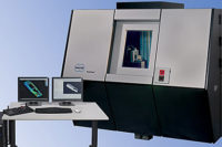
A multi-sensor coordinate measure machine with X-ray computed tomography can make accurate measurements during the first out of tool inspection, as well as for the full first article inspection.
This approach’s basic concept is to obtain a 3-D point cloud of the entire part with all surfaces and inner geometries including voids. The point cloud can be evaluated by software for any type of application—inspection, first out of tool testing and complete first article inspection.
The principle of X-ray CT
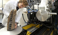
X-ray computed tomography is an appropriate technology for complete acquisition of components without part preparation or destruction. Originally developed for medical technology, this process places the object on a rotary table between an X-ray source and a detector. The detector works similarly to a CCD camera. A series of X-ray images of the object are taken at numerous rotary table positions. A mathematical process allows reconstruction of the spatial contour of the component from the X-ray images. The 3-D image resulting from the reconstruction consists of volume elements (voxels), each of which has a density value that indicates the radiation absorbed by the component within the voxel volume. The reconstructed volume model describes the complete geometry of the work piece, including interior geometry and undercuts of very complex components. By changing the distance between the work piece and the detector, and the work piece and the X-ray source, different magnifications and measurement ranges can be obtained Either precise acquisition of small parts at high magnification or rapid acquisition of larger parts at lower magnification is possible.
For dimensional measurements, the part surface is extracted from the volume image. The definition of the material boundary required for this directly influences the precision obtained. It must therefore be done very carefully and automatically.
The precision obtainable in computer tomography is limited by a large number of additional influences. Disturbance effects in the volume image (artifacts) can occur that lead to false interpretation and depend on the radiation wavelength, geometry and work piece material. These are difficult to correct. In addition, a large number of system parameters are unknown or not constant, such as the location and size of the burn pattern of the radiation source and the material properties of the work piece. Up to now the precision that has been obtainable using computer tomography has not been sufficient for functional dimensional inspection.
When computer tomography is combined with precision sensors, rapid, complete work piece acquisition is possible using tomography along with exact measurement with classical sensors and recalibration of the CT point cloud. This technique has lead to a multi-sensor coordinate measuring machine with high accuracy computed tomography. The CMM provides the capability of combined measurement with sensors familiar from multi-sensor coordinate measuring machines and computed tomography in a uniform coordinate system. In addition to precise measurements of the exterior work piece geometry, it is possible to evaluate and document characteristics on the interior of the work piece using existing contour image processing.
The arrangement of mechanical axes allows combined measurements with maximum flexibility. Using multiple slide axes, separate positioning of the X-ray detector and other sensors is possible. Separate positioning of the radiation source and detector allows variation in the magnification of the computed tomography.
A new approach: highly accurate measurement by correcting the CT point clouds
If the same areas are measured using several sensors, the measurement results provided by the various sensors can be compared to one another. The measurement results from the less precise sensor are corrected using the more precise information. A new type of mathematical application, based on this concept, allows correction of process related errors in computed tomography. This is done by acquiring reference points on the work piece with a high precision sensor and correcting the surface of the CT generated point cloud so that the variation between the reference points and the CT point cloud are minimized. This allows the acquisition of measurement points using computed tomography at a quality that had previously been out of reach.
Traceability of tomographic measurements can be implemented directly on the measured object using proven sensors from multi-sensor CMMs. The precision specification of the instrument is in accordance with standards and guidelines for coordinate measuring machines (ISO 10360 / VDI 2617), so that it can be compared with typical measurement machines. Length measuring error when using the appropriate sensors and magnifications is, for example, E3 = 4.5 + L/75 µm. Introduction of this technology is made easier by the ability to take tactile comparative measurements, since proof of the accuracy of the measurement results can be obtained at any time.
Also, the CMM has the ability to expand the computed tomography measurement range using raster tomography. In such cases, several partial images are taken and combined into a larger image and reconstructed into the complete image of the part.
A new machine, that uses air bearings for the highest precision requirements and for measuring micro-components, is also available. The maximum permissible error for length measurements for this device, based on ISO 10360 and VDI/VDE 2617, is specified as E3 = 1.5 + L/500 µm. This newer equipment is particularly suited for a combination of CT with additional sensors such as a Fiber Probe and laser because of the high fundamental precision of the basic machine design. Rapid checking of internal dimensions of plastic parts and other work pieces with complex geometries are now available through continued industry innovations.
Looking for a reprint of this article?
From high-res PDFs to custom plaques, order your copy today!


