Air Gaging
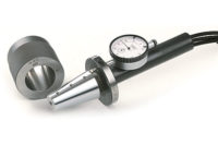
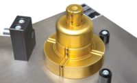
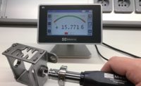
Air gages provide reliable, repeatable measurements.

Source: Western Gage Corporation

Source: Western Gage Corporation

Source: Western Gage Corporation

Source: Western Gage Corporation


Air gage systems use a precision orifice (jet) at a specific distance from the surface being measured and regulated air pressure to create a pressure-distance curve. As the clearance between a part and the tooling’s jets is reduced, air flow is reduced and back pressure increases. This pressure distance curve is then interpreted into a displacement and displayed on a readout device.
The tool is designed to examine total tolerances of typically 0.005 inches or smaller, with abilities to measure to the millionth of an inch, according to Air Gaging, LLC President Chris Koehn.
“For high-volume, tight-tolerance applications, an air plug is a very good way to go,” says George Schuetz, director of precision gages for Mahr Federal. “Plus … the air tends to blow away water-based contaminates and so forth and cleans out the part as it makes the measurement.”
Another benefit is the lack of operator influence on the measurement, unlike a caliper or micrometer where the user has to maintain a consistent angle and approach for each part.
“With an air plug you just stick it in the hole and you make the measurements,” Schuetz continues.
In addition, because air gages are non-contact, they are suitable for inspecting soft and thin-walled materials.
Single Master or Min-Max Master
There are two philosophies for calibrating an air gage before measurement. One is to use a single master to zero the gage, and the other is to use two masters to set a min-max range.
“If you can precisely control the jet characteristics, its clearance to the part and the air pressure, you create a very accurate and repeatable pressure distance curve.” explains Schuetz. “So with this concept, a zero master puts the air system in the very mid-point of that pressure distance curve and ensures high performance throughout its measuring range.”
The other method uses two masters to set a min-max value.
“Now you have two slightly different back pressures, depending on how far apart those tolerances are,” explains Koehn. “And to put it real simply, the column or the readout is like a calculator at that point.”
Markets
Koehn says his most common customer works in high-production and is looking for high-precision.
“They want to inspect 100 percent of the pieces and then track them,” he says. “Some of our software has SPC built into it, so they can statistically track all of the pieces. That’s probably the No. 1 type of customer that’s coming to us is high-production round parts.”
Automotive remains one of the largest high-production users of air gages, along with aerospace and medical.
Koehn says his second largest customer category looks for ways to explore the complex internal geometry of a part faster than they would with a CMM.
Rather than the approximate 15 minutes it would take a CMM to check the taper of an artificial hip, for example, an air gage can read the measurement in a few seconds because its tooling has been made specifically for the task.
Limitations
Air gages work best with smooth parts.
“If you have a rough surface, the air has to fill in all those valleys on the surface on the part. So if you have a very rough part, you can get a variation between the peaks and what the air gage is measuring,” Schuetz says.
Another limitation is that air jets on the tooling must be totally covered by the part. Meaning, “You can’t measure right up to a corner of a surface, you have to measure some distance away from that surface, again to make sure the jet is totally covered,” he continues.
An additional limitation pointed to by Koehn is the lack of range. If a manufacturer has the same part in three different sizes, differing by a half inch each, it will require three different air plugs.
“And that’s the downside versus contact gages,” he explains. “Maybe a dialed bore gage will give you a half-inch to an inch of range. We only have a few thousandth (of an inch) of range.”
That limitation is balanced by the fact that, as previously mentioned, air gaging is fast, and almost no operator error is possible with the air gage.
“If you have a dial bore gage and you have three operators, they will all get slightly different readings depending on how perpendicular they held the dial bore gage to the surface they were measuring,” he says. “An air gage doesn’t have that problem. Multiple operators will get nearly the same reading, within the repeatability of the gage.”
Evolution
While the general principles behind air gaging have remained constant, improved computer processing and other advancements have allowed the technology to evolve and grow in the number of suitable applications in recent decades.
“The math functions that can be done, you can check a lot more things, you can show degrees, minutes, seconds of an angle,” Koehn says. “You can do any kind of calculation that you want. You might take several diameter readings, even on one plane, and average them together. They’re not just the old glass tube style anymore where it just tells you what the diameter is of the particular plane that you’re checking. It really has evolved to become more of a tool that can give you some correlation to a CMM.
“We also do scanning with air gages. We can actually scan the contour of a part. We’ll do this in fuel injection. They actually scan and literally get hundreds of data points and it will actually draw the contour and pick out those features that they want to check. So in that circumstance, the air gage has become much more than what an air gage was initially designed for.”
Looking for a reprint of this article?
From high-res PDFs to custom plaques, order your copy today!


