If you need less sliding friction, should you make the surface rougher or smoother?
Think quick!

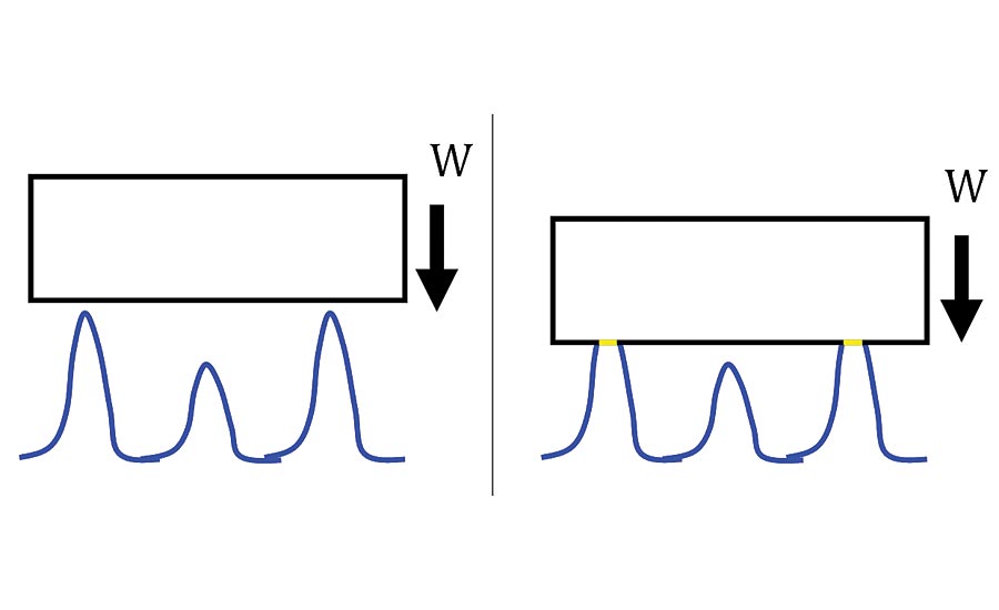
Figure 1. Asperities making plastic contact with flat, smooth, rigid, hard plate with load (i.e. weight), W.

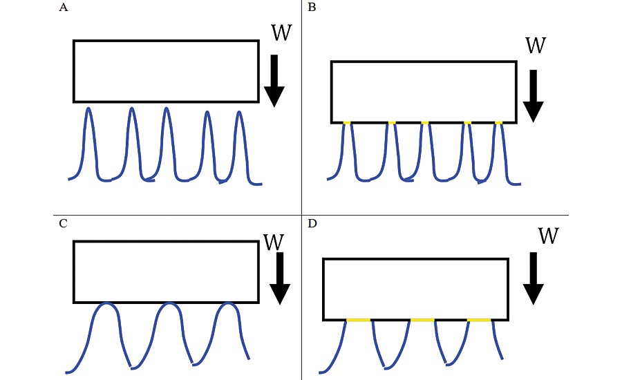
Figure 2. When small radii asperities make contact elastically with a flat, smooth, rigid/hard surface (A-B) the real area of contact is smaller compared to larger radii asperities making contact (C-D).

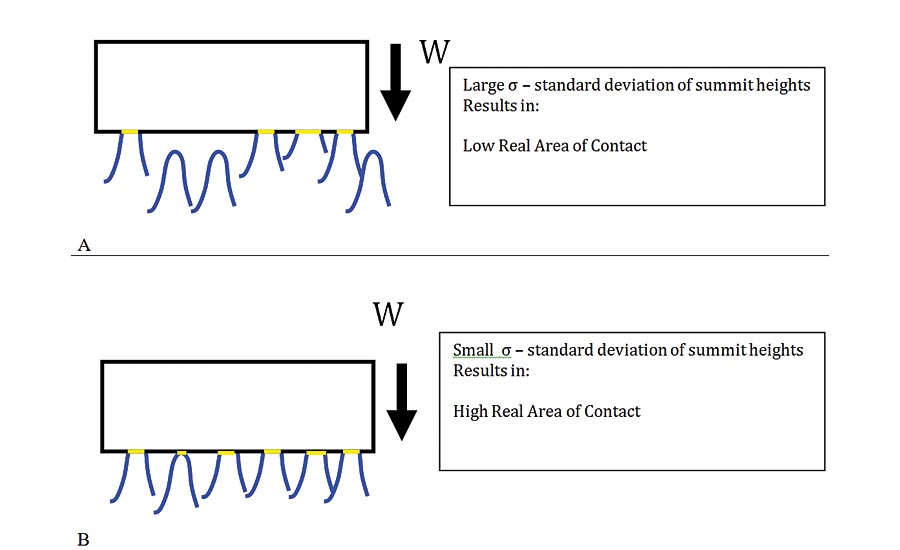
Figure 3. For a large standard deviation of summit heights, the real area of contact is lower (A) than for a small standard deviation of summit heights (B), for the same summit radii, materials and load.

Figure 4. 3D surface texture measurement of a sliding surface that initially started in a highly rough condition resulting in some degree of plastic deformation/plowing (A) and thus high friction. After running-in the resulting surface tended to stabilize in an “elastic” regime of contact and thus some moderate sliding friction (B). Toward end of life as the surface was further polished the lower roughness resulted in a higher real area of contact and thus higher friction (C).

Figure 5. A Universal Mechanical Tester (UMT) used to measure friction between various test components (A) and a typical friction vs. load measurement performed with a ring on cylinder configuration (B). The red curve and blue curve are for different lubricants that were tested.


How does the surface texture affect the friction between two dry parallel sliding surfaces? It turns out that this problem has challenged some of the greatest minds in science and engineering. The key understanding of the relationship of dry sliding friction to surface texture is linked to the notion of the “Real Area of Contact.” As stated by Frank Phillip Bowden, a pioneer in the field of tribology: “…putting two solids together is rather like turning Switzerland upside down and standing it on Austria – their area of intimate contact will be small” (1950).
The work by Bowden and Tabor established the idea that dry sliding friction is coming from the shearing of the junctions being formed at the regions of intimate contact (i.e. real area of contact) of the mating sliding surfaces. Depending on the surface roughness (e.g. as measured by Ra – average roughness) and the material properties, the real area of contact may not be too dependent on the surface roughness—in other words, if you make the surface “rougher” or “smoother” you may not affect the sliding friction.
On the other hand, for various types of texture and materials the nature of the surface roughness may affect the dry sliding friction. In some case, making the surface smoother will reduce the friction, whereas in other cases, making the surface rougher will reduce the friction.
Are you confused yet?
Surfaces under Plastic Deformation
Consider a perfectly flat, smooth, rigid/hard, plate with load (i.e. weight), W, being brought into contact with a surface comprised of asperities which constitutes the surface
texture (Figure 1). If the contacting asperities undergo pure plastic deformation (Note that the plate is perfectly rigid/hard and so there will be no localized deformation at the plate surface) then each asperity can only “push” back on the mating surface with a force equal to the material hardness, H (i.e. measured in Newton/m2) multiplied by the real area of contact at the junction, Arp (i.e. measured in m2). Thus a number of asperities will need to make contact so that the total force pushing up by the individual asperities equals the load, W, pushing down by the flat, rigid and smooth surface. Thus the real area of contact necessary to support the load will be given by:
Arp = W/H Eq. 1
where H is the hardness of the materials comprising the asperities.
The sliding friction, for plastic deformation, Fp is then given by:
Fp = ArpS Eq. 2
Where S is the shear strength (measured in Newtons/m2) of the junctions formed at the asperity contacting regions.
Note that the equation for the frictional force for plastic deformation, Fp only depends on the shear strength of the junctions (i.e. a material system property), and the real area of contact. Also, the real area of contact only depends on the force between the surfaces (W) and the hardness (H). So actually the friction force, under plastic deformation has no dependence on anything related to the “roughness” of the surface. In fact this simple relationship demonstrates no dependence on the nature of the asperities such as their radius of curvature, asperity, density etc.
So indeed, in the case of plastically contacting surfaces you are out of luck! You can’t reduce the friction by either making the surface rougher or smoother!
Surfaces under Elastic Deformation
Typically, once a sliding surface has run-in for a while there is some change to the texture and the surface material properties (e.g. work hardening) and thus the asperities may begin to support the load elastically. About 50 years ago, Greenwood and Williamson (GW66) developed the model by which surface asperities support the load elastically and further extended our understanding of sliding friction. Under pure elastic deformation, a relationship between the real area of contact, Are and various surface and material properties is given by:

Where, W is the load between the surfaces,
E is the elastic modulus of the asperity material (note for the top rigid plate E~∞)
R = average radius of curvature of the asperities
σ = the standard deviation of the asperity heights (related to the average roughness)
The sliding friction, for elastic deformation, Fe is then given by:
Fe = AreS where is S is the shear strength (measured in Newtons/m2) of the junctions formed at the asperity contacting regions.
Thus for pure elastic deformation at the asperities, the sliding friction does have a dependence on the surface texture since the real area of contact depends on the nature of the texture.
If the asperities have small radii, R, (e.g. “needle type”), assuming elastic deformation, the real area of contact will be small and thus the sliding friction reduced. If however the asperities have large radii, R (e.g. “balloon type” structures) the real area of contact will be larger and thus the friction will be higher (Figure 2).
Figure 3 demonstrates the dependence on the real area of contact
(and thus sliding friction) on the standard deviation of the summit heights (i.e. related to the average roughness, Ra). For surfaces composed of a large summit height deviation (i.e. high Ra – rough surface) the real area of contact may be small resulting in low sliding friction, whereas a low Ra surface (i.e. smaller deviation of summit heights) will result in a higher real area of contact and thus higher friction.
Thus, assuming elastic deformation at the points of contact, adjusting the surface texture by modifying the asperity localized radii and/or overall average roughness will affect the friction. In the elastic regime, lower roughness, Ra will usually result in a larger real area of contact and thus higher friction.
So indeed, in the case of elastically contacting surfaces the solution to reducing the friction is to “make the surface rougher!”
Hard Rough Surfaces and Plowing
A final regime to consider is when the flat, smooth, plate making contact with the asperities is not rigid/hard but has finite material properties in which the contacting asperities begin to plow into the plate. This conditions may happen when an unintended rough surface texture (i.e. the asperity side) is coated with some hard material (e.g. a diamond like coating), making the asperity side of the interface appear as a “saw” to the flat smooth surface.
Bhushan developed an estimate of the friction coefficient uplow (i.e. Fplow/W) for asperities with radius R, penetrating a depth, d into a mating surface as:

Thus the smaller the radii, R of the plowing asperities, and the higher the average roughness (i.e. asperity distribution number and height), the more plowing. More plowing will result in a higher the friction coefficient, uplow, and thus higher sliding friction force.
So when a rough surface is plowing into a mating surface resulting in high friction it is best to lower the surface roughness and make the summit radii larger to reduce the friction.
So indeed, for plowing type frictional mechanisms the solution to reducing the sliding friction is to “make the surface smoother!”
Figure 4 demonstrates measurements made with a 3D optical profiler of a surface under sliding conditions that evolved from the plowing (A) mechanism (i.e. high sliding friction), through to the plastic mode (B) of deformation (i.e. moderate degree of sliding friction), to the elastic mode (C) where the real area of contact had greatly increased (i.e. high degree of sliding friction—possibly seizure with mating surface).
The Multi-Asperity Model and Beyond
The models discussed above for sliding friction are all for situations when the contacts are being made at isolated, non-connected islands scattered throughout the apparent contacting objects.
A breakthrough in understanding sliding friction and the real area of contact occurred around 2001 when Persson establish a theory which can predict the area of contact beyond the multi-asperity model. Persson’s work further demonstrated how the nature of the surface texture, expressed by characteristics related to the amplitudes and spacings will affect the real area of contact from the regimes described by the mechanisms discussed above to full 100% contact between the mating surfaces.
Measurement Systems
The measurement of the friction between sliding surfaces may be readily performed with various instruments. Figure 5 demonstrates the universal mechanical tester (UMT) which has many optional modules that allows for different friction system simulations. Using systems like the UMT the friction forces (or frictional coefficient, COF) may be measured as a function of various conditions such as load, distance traveled, degree of lubrication etc. Q
Future Study
Lectures reviewing the work discussed above may be found at:
https://www.youtube.com/watch?v=JwMOsgP046I
https://www.youtube.com/watch?v=1zuLyVddqx0&feature=youtu.be
http://www.multiscaleconsulting.com/our-research/contact-mechanics
Looking for a reprint of this article?
From high-res PDFs to custom plaques, order your copy today!


