Quality 101
Pre-Plate Threads: 60° Thread Form
Nobody wants to make or sell a custom gage you can’t use and are unable to return.

Image Source: Surasakpd / iStock / Getty Images Plus
As with all gages and inspection tools, the functionality and accuracy of the product thread or the gages used to inspect them, is heavily dependent on the information supplied from the product manufacturer, engineer, or designer. The product design and tolerances always dictate the dimensions and tolerances for the gage used to inspect them. When we apply plating to a thread form, the thread geometry is affected. The changes to the thread pitch diameter are significant. The key to understanding and creating the proper pre-plate allowances is to correctly compensate for the buildup on all surfaces of the thread form. For instance, a 60° UN thread pitch diameter will change 4X the plating thickness. If the thread form angle changes to a 29° ACME, the plating change for the pitch diameter increases to 8X. We will focus on 60° Threads for this discussion.
The ASME B1.1-2019 for “Unified Inch Screw Threads (UN, UNR, and UNJ Thread Forms)”, Section 7 and the ASME B1.13M-2005, “Metric Screw Threads: M Profile”, section 8, both show formulas for calculating the pre-plate product dimensions for the 60° thread form pre-plate product threads. There are limitations to these formulas. They do not apply to dipped coating, paint, or other “heavy” plating or coatings. Both standards have suggestions for using standard thread tolerance classes. See the above-mentioned standards for further information on these options. We are only focusing the math calculations based on the plater supplying the minimum and maximum plating thickness.
Below is an illustration (Fig. 1) of how plating builds up on the flanks of the thread form. It shows the effects of the coating on the pitch diameter of the thread.
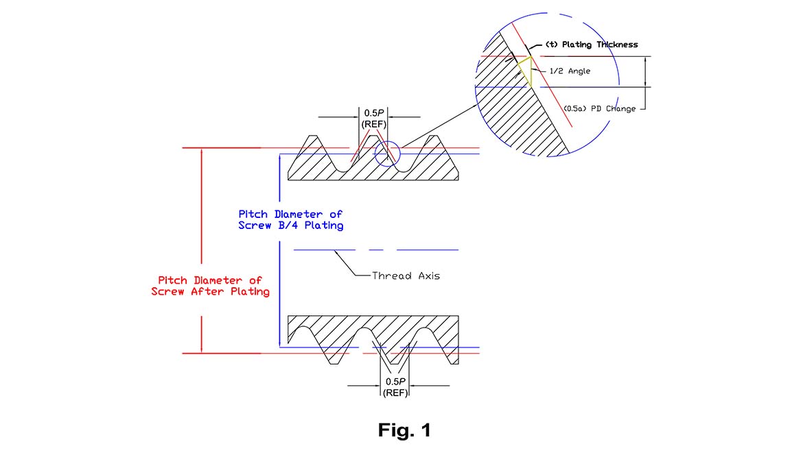
The pitch diameter change due to plating on a Unified Inch or M Series Metric 60° screw thread is 4X. The formula is:
a = 2 (CSC 1/2 Angle)
a = 2 (CSC 30°)
a = 2 x 2 = 4
If you have a 0.0002” plating thickness, the change in pitch diameter is (4 x 0.0002” = 0.0008”), Fig. 2. Does this mean that both my minimum and maximum pitch diameter will both be decreased by 0.0008” on an external product thread? Unfortunately, no, this is only the beginning of the calculations. We also need to account for plating provider’s tolerance for their plating process thickness. We take this 4X plating and apply it to the plater’s minimum and maximum plating tolerances. These values are then applied to the product thread pitch diameter.

See the example below:
After Plate Dimensions:
¼-20 UNC 2A external product thread:
Pitch Diameters = 0.2164” / 0.2127”
Plating = 0.0002” – 0.0004”
Product Thread Pitch Diameter Formulas per ASME B1.1-2019:
Max Pre-plate PD = Max After Plate PD – (4 x Max Plating Thickness)
= 0.2164” – (4 X 0.0004”)
= 0.2164” – 0.0016”
= 0.2148” Max Pre-plate PD (Go Ring or Setting Plug PD)
Min Pre-plate PD = Min After Plate PD – (4 x Min Plating Thickness)
= 0.2127” – (4 X 0.0002”)
= 0.2127” – 0.0008”
= 0.2119” Min Pre-plate PD (No-Go Ring or Setting Plug PD)
The above examples only apply to the pitch diameter of the external product thread. If the product thread is internal, the plating will increase the pitch diameter of the nut or internal product pitch diameter before plating.
See the formulas below:
After Plate Dimensions:
¼-20 UNC 2B internal product thread:
Pitch Diameters = 0.2175” / 0.2224”
Plating = 0.0002” – 0.0004”
Product Thread Pitch Diameter Formulas per ASME B1.1-2019:
Min Pre-plate PD = Min After Plate PD + (4 x Max Plating Thickness)
= 0.2175” + (4 X 0.0004”)
= 0.2175” + 0.0016”
= 0.2191” Max Pre-plate PD (Go Work Plug PD)
Max Pre-plate PD = Max After Plate PD + (4 x Min Plating Thickness)
= 0.2224” + (4 X 0.0002”)
= 0.2224” + 0.0008”
= 0.2232” Min Pre-plate PD (No-Go Work Plug PD)
Once you have the calculated pre-plate minimum and maximum pitch diameters, you can request pre-plate gages based on the pre-plate pitch diameters. Purchasing gages for the pre-plate threads can be a challenge. Gage end users will sometimes only supply the amount the tap is oversize to create the plated product internal thread. This will not work and using the amount oversize from the cutting tool and applying it to both the minimum and maximum gage pitch diameters equally will cause the gage user to accept out of tolerance threads or scrap in tolerance threads. (See the previous Quality article from 11/2023 for more information on Taps vs. Gages How Do Tap Limits Affect Gage Selection?)
Metrology labs will measure the gages based on the pre-plate pitch diameters marked on the gage members or handles. The problems arise when the lab measures the pre-plate major diameter on working thread plug gages, minor diameters on thread ring gages and the full form major diameters on truncated thread setting plugs. There are differing opinions in the industry on the calculation of the gage major and minor diameters. Some use the custom calculated pre-plate pitch diameters and add the standard calculations for major and minor diameters in the ASME gage standard. (This results in an effective 4X change to the major and minor diameters.) Others will follow the ASME product thread standard and apply the 2X change to the major and minor diameters. The 2X on major and minor diameters follows the product thread ASME B1.1-2019 and ASME B1.13M-2005.
There are many other variables that will affect how you order, use, or calibrate pre-plate thread gages. Some coatings, such as anodize plating, will penetrate the substrate up to 50%. If you apply 0.0002” the buildup is only 0.0001”. If you only have a minimum or nominal plating thickness, there are ASME B1.1 & B1.13M calculations to assist. If your calculation generates a minimum and maximum pitch diameter less than 0.0015” between them, the thread plug gages will not work. The gage dimensions would be too close together to allow the inspector to feel the difference between the Go and No-Go gage. If you are quoting or ordering any custom gages be sure to ask your supplier for a gage spec sheet. Most gage manufacturers will offer them. This sheet will show the manufacturer’s suggested gage dimensions and tolerances. This can save you time and money by reviewing and confirming or altering prior to placing an order. Nobody wants to make or sell a custom gage you can’t use and are unable to return.
Looking for a reprint of this article?
From high-res PDFs to custom plaques, order your copy today!


