Test & Inspection
Common Problems in Microhardness Testing
By using properly maintained and calibrated equipment, trained personnel, and appropriate testing environments, these problems can be minimized.


By their nature, microhardness testers are delicate instruments. Extremely light forces (typically from 10 to 1,000 g.) must be accurately applied, and the resultant impressions (some as small as 10 microns) must be precisely measured under high magnification. And so there are a number of problems inherent to all of them.
When people think of microhardness testing, three terms often come to mind: finicky, subjective, and time consuming. In many cases, all three of these connotations are well deserved. Fortunately, advances in computer technology have reduced, if not eliminated, them as issues. In addition, there are the problems of accuracy, repeatability and correlation that are inherent to microhardness testing. However, by using properly maintained and calibrated equipment, trained personnel, and appropriate testing environments, these problems too can be minimized.
Three Basic Problems
Microhardness testing problems can be separated into three categories: accuracy, repeatability and correlation, and can be traced to five main causes: machine, operator, environment, sample preparation, and calibration. And, while there are really only five major causes, there are numerous issues encompassed by each. The most common are discussed below.
The Machine
Microhardness testers use dead weights to create force. Unlike Rockwell hardness testers, these light loading devices (10 to 2,000gf) stack the dead weights directly on top of the indenter. This eliminates the error of magnification and a lot of other negatives, such as knife-edges and hanging weights. Other units utilize screw drives to apply force, and load cells to control the amount of force applied. These types have their own set of repeatability and durability issues. Generally, these force application systems are robust. However, issues of indenter stroke can create erroneous loads.
With most machines, load application is done in two speeds: a “fast speed” to bring the indenter close to the test piece and a “slow” speed to contact the work and apply the load. The “stroke” of the indenter is usually set with a measuring device. Once this “indenter tip to test surface” distance is set, the high power objective is focused on the test surface. Once properly focused, the operator is assured the work piece is contacted at the proper speed, and that impacting of the load has not occurred. It takes approximately 30 seconds for an instrument to make an impression, considering ASTM E384 standard dwell time of 15 seconds. This is part of the “slow” problem mentioned previously.
Alignment of the indenter with the objectives is critical when measuring case depths or just trying to accurately place an impression on a specific spot. Although the accuracy of the hardness value is not affected by this error, if the operator is measuring effective case depth, the distance from the edge of the sample may be wrong and result in an erroneous measurement.
Also, if the operator is attempting to make an impression on a particular grain, or in the center of a thin coating, misalignment can make this difficult, if not impossible, to accomplish. Knocking the indenter or the objective with the sample can cause misalignment, so care must be taken when loading samples or rotating the turret.
The Operator
No other discipline of hardness testing is influenced as much by the operator as microhardness. Although this is true for both Vickers and Knoop testing, Knoop testing with its fine, seemingly endless tips is the most susceptible.
In general, the ability of an operator to accurately and repeatably resolve the ends of the impressions most often is the cause of error. Getting two operators to agree exactly, when measuring the same impression, is indeed rare. This problem is often masked by users performing daily verifications of their machines. Here, operators can take their time measuring these impressions on test blocks of a known hardness whose test surfaces are typically in the optimal condition. In production environments, operators are sometimes rushed to perform tests and get parts out the door. All the care that was taken to ensure the proper results on the hardness standard is nowhere to be found.
TECH TIPS
Microhardness testing problems can be separated into three categories: accuracy, repeatability These problems can be traced to five main causes: machine, operator, environment, sample preparation, and calibration. In addition, there are numerous issues encompassed by each. |
Additionally, it can be a mundane and tiring task looking through the eyepiece for any period of time. Often, the operator mentally knows the proper dimension of the impression and, when he goes to measure it, he “sees” that value, which is human nature. Proper focus is critical in achieving accurate results. As blurriness increases, so does perceived image size. Consistency of focus helps increase consistency of results. Most automated systems feature some means of focusing automatically, virtually eliminating this concern.
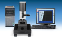
Recording and converting results from microns to Vickers or Knoop hardness numbers is another common source of error. Digital microhardness testers that utilize optical encoders that assist with measuring help to eliminate this error. However, they do not find the impression ends. To help eliminate these problems, cameras can be attached to virtually any microhardness tester, as well as most of the “vintage” models. These cameras feed an image to a computer, which enables the operator to view the image on the computer’s monitor.
Here, Vickers and Knoop impressions can be measured manually by clicking the mouse on the corners of the impression, or in more sophisticated software, the computer will perform a form of gray scaling to automatically determine the tips of the impression and display the hardness value, converted scale (HRC, etc.) and typically the average diagonal.
The enhanced magnification afforded by the camera and the monitor enable the operator to more precisely resolve the tips of the impressions. Also, viewing impressions on the monitor is far more comfortable and relaxing than squinting through an eyepiece, thereby reducing operator fatigue.
Modern modular systems can go from a basic “click on the tips” type of a system all the way through to full automation. This enables users to seek the sophistication level that best matches their needs and, should requirements change, allows their system to grow. Operating in a Windows environment, this type of system collects, files, and stores the data, eliminating errors of transposition or data co-mingling.
Automatic measuring is one of the most popular features of this system. Operator influence over the measurement of impressions is eliminated, as is the sometimes time-consuming process associated with measuring. Once the operator clicks on the “measure” icon, the image is captured and the impression is measured in a blink of the eye. Actual diagonal length, hardness value, and converted scale are displayed on the screen, and saved to a file.
The Environment
Because of the light loads utilized in microhardness testing, vibration can contribute to loading accuracy. Even if the part is not impacted during loading, the oscillation of the indenter or the test specimen can cause the indenter to work its way deeper into the part, creating a softer result.
Microhardness testers should be placed on a dedicated, level and free-standing table that is appropriately located away from slamming doors or adjoining walls and tables that might create vibration or movement that is translated through the table.
Microhardness testers often utilize high magnification optical systems to assists operators in defining the small tips of impressions. Dirt in the optical path (the ocular, optical encoder, tube, or objective) can obscure the impression or the measuring lines. A clean environment helps diminish the chance this occurs. Common sense also goes a long way. Cutting, grinding or polishing samples, for example, should be avoided in the immediate area of the tester.
Sample Preparation
In most cases, samples are sectioned and mounted prior to testing. The samples are then ground, sanded and polished to provide a test surface free of scratches and surface texture. Sometimes production demands do not allow an operator to spend the time necessary to realize a proper finish. This often results in undulating surfaces, rounded edges that are difficult to discern, or surface imperfections that make it difficult to accurately measure the tips of the impression.
When etching samples, the surface of the part is chemically corroded, providing metallographic contrast. Although it helps define grain structure, heat affected zones in welds, total case depths and decarb layers, the etching of samples lessens the contrast between the test surface and the tips of microhardness impressions. In many cases this diminished contrast can make it difficult or impossible to measure the impression. If microhardness testing is performed on an etched sample, it should only be the minimum etching required to visually discern the desired attribute.
Although most automated micro-hardness testing systems can automatically measure Vickers and Knoop impressions repeatedly on finely prepared samples, many systems are fooled by surface anomalies and changes in contrast. Systems that utilize “thresholding” techniques to determine the impression size are the most susceptible to these issues and exhibit the greatest amount of variation and error.
Calibration
Most microhardness testers lead a charmed life in comparison to Rockwell and Brinell testers. They usually wind up in laboratory environments, free from the dirt and oil that can plague other hardness testers. Consequently, microhardness testers tend to have long useful lives, with little to go wrong between calibrations.
Fortunately, most microhardness testers are very consistent in their ability to apply force, and, with the exception of load cell units, there rarely is an issue when it comes to calibration.
While measuring systems in micro-hardness testers vary widely, ranging from micrometer heads on an ocular, to optical encoders attached to a digital readout, they have one thing in common. They depend on being at a specific magnification, or distance from the objective (the ocular slides in/out to increase/decrease magnification). If not careful, measuring accuracy can be compromised.
To directly verify the measuring system, a stage micrometer is placed on the anvil, and the instrument’s measuring lines are place at a known distance on the stage micrometer. This distance is then compared to the unit’s measuring system. If they agree, all is well. If not, the ocular is moved in or out to increase or decrease the measuring distance.
Microhardness testers usually are indirectly verified against standard hardness blocks. As the resultant impressions are extremely small, these standard blocks can appear to last forever. But, if improperly handled, blocks can become scratched making them difficult to read, emphasizing the need to check multiple standard hardness blocks.
Since microhardness testers’ impressions reside in very thin sections of the test surface, it is important that test blocks are calibrated in the forces that are typically used. Test block values should only be considered at the forces at which they were calibrated. This means that it is inappropriate to use Rockwell blocks and convert them to Vickers or Knoop values.
Properly used and maintained, microhardness testers are invaluable tools. Taking the time to review the recommendations made in this article will lead to more credible results and better process control.
Looking for a reprint of this article?
From high-res PDFs to custom plaques, order your copy today!


